
Tubular xenon lamp circuit

The tubular xenon lamp is a high-intensity discharge (HID) light source, characterized by its ability to produce a bright white light that closely resembles natural sunlight. This lamp operates by ionizing xenon gas within a glass tube, leading to the emission of light when an electrical current passes through the gas. The design of the lamp typically includes a tubular shape to maximize the surface area for light emission and to facilitate effective heat dissipation.
The wiring configuration for a tubular xenon lamp involves several key components. The lamp is connected to a high-voltage power supply, which is essential for initiating the ionization process. This power supply usually incorporates a ballast to regulate the current flowing through the lamp, ensuring stable operation and preventing damage due to fluctuations in voltage.
In a typical circuit schematic for a tubular xenon lamp, the following elements are present:
1. **Power Supply**: A high-voltage source, often in the range of several kilovolts, is necessary for starting the lamp. This power supply may include a transformer to step up the voltage and a rectifier to convert AC to DC if required.
2. **Ballast**: A ballast is employed to limit the current once the lamp is ignited. This component can be an electromagnetic or electronic ballast, depending on the design requirements. The ballast ensures that the lamp operates within its specified current range, optimizing performance and longevity.
3. **Ignitor**: An ignitor may be included in the circuit to provide a high-voltage pulse that helps initiate the arc within the xenon gas. This component is crucial for starting the lamp and is typically activated momentarily during the ignition phase.
4. **Lamp Socket**: The lamp is mounted in a socket that provides electrical connections to the power supply and ballast. This socket must be designed to withstand the high temperatures generated during operation.
5. **Cooling Mechanism**: Due to the high brightness and heat generated by the lamp, a cooling mechanism, such as a fan or heat sink, may be integrated into the design to prevent overheating and ensure consistent performance.
The schematic diagram referenced as Figure 2-6 would illustrate these components and their interconnections, providing a visual guide for proper wiring and assembly of the tubular xenon lamp circuit. The arrangement of components should be designed to minimize electromagnetic interference and ensure safety during operation. Proper insulation and protective casing are also essential to safeguard against electrical hazards.Tubular Xe lamp power, high brightness, known as the "little sun." Tubular xenon lamp wiring shown in Figure 2-6.
Related Circuits
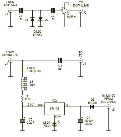
This wideband amplifier circuit is designed using the MAR-6 IC manufactured by Mini Circuits. The MAR-6 VHF-UHF wideband amplifier circuit provides a stable gain of at least 9 dB up to 2 GHz. Since the MAR-6 is designed to...
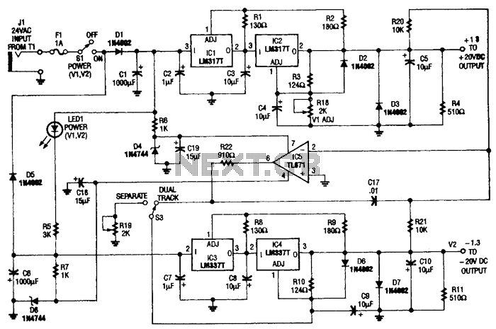
This circuit is useful for a bench supply in the lab. Separate or tracking operation is possible. The regulators should be properly heatsinked. Tl is a 24-Vac wall transformer of suitable current capacity. The described circuit functions as a laboratory...
The EUA2032 is a high-efficiency, 2.5W mono class-D audio power amplifier. A newly developed filterless PWM modulation architecture further reduces EMI and THD+N, as well as eliminates the LC output filter, thereby reducing the external component count, system cost,...
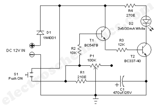
The 555 adjustable timer circuit initiates timing upon activation. A green LED illuminates to indicate that the timing process is underway. Once the designated time period concludes, the... The 555 timer IC is a versatile device widely used in various...
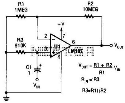
A general-purpose noninverting AC amplifier for audio and other low-frequency applications is presented. Design equations are included in the figure. Almost any general-purpose operational amplifier can be utilized for U1. The circuit configuration features a noninverting amplifier topology, which is widely...
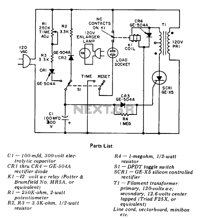
This precision solid-state time delay circuit features both delayed off and delayed on switch functions, which can be interchanged by simply swapping the relay contacts. The described time delay circuit is designed to provide precise control over the timing of...