
OP90 4 mA to 20 mA Current Loop Transmitter

The current transmitter operates within a specified range, providing an output current that is directly proportional to the input voltage. This is typically used in industrial applications for process control, where it translates varying voltage levels into a standardized current signal for further processing or monitoring.
The output range of 4 mA to 20 mA is a common standard in industrial automation, allowing for easy integration with various control systems and devices. The lower limit of 4 mA usually indicates a zero input voltage, while the upper limit of 20 mA corresponds to the maximum input voltage. This linear relationship ensures that any changes in the input voltage result in a corresponding change in the output current, which can be easily measured and interpreted by downstream devices.
Line rejection refers to the ability of the current transmitter to filter out noise and interference from the power supply or other external sources. This ensures that the output signal remains stable and accurate, even in environments with fluctuating electrical conditions. Effective line rejection is crucial for maintaining the integrity of the signal, particularly in applications where precision is essential.
The schematic of the current transmitter would typically include components such as operational amplifiers, resistors, and capacitors configured to achieve the desired gain and linearity. The input stage may include a differential amplifier to accurately measure the input voltage, while the output stage would be designed to convert this voltage into the specified current output, often utilizing a transistor or a current loop driver.
Overall, this current transmitter is an essential component in many electronic systems, providing reliable and accurate signal conversion for various applications.An output of 4 mA to 20 mA that is linearly proportional to the input voltage is provided by the current transmitter on figure below. Line rejection is. 🔗 External reference
Related Circuits
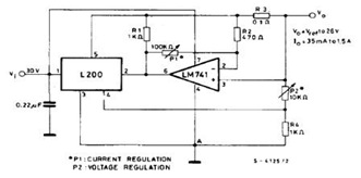
The datasheet contains application circuit diagrams for the L200, including a Programmable Voltage Regulator, a High Current Voltage Regulator with Short Circuit Protection, a Digitally Selected Regulator with Inhibit, a Programmable Voltage and Current Regulator, a High Current Regulator...
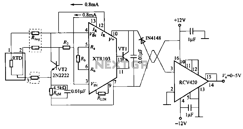
When the RTD temperature sensor is positioned far from the amplifier, the resistance of the sensor leads and their susceptibility to interference and other issues cannot be overlooked. The circuit shown in the figure addresses this problem. It utilizes...
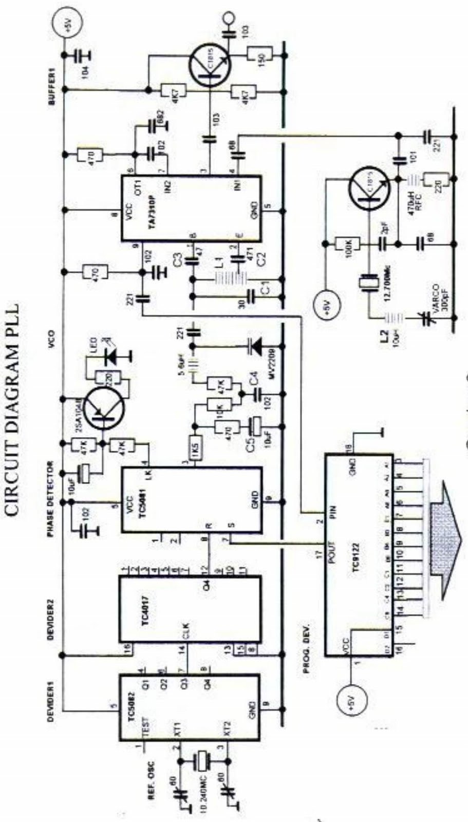
The primary function of the phase-locked loop (PLL) phase detector is to compare the input phase of the voltage-controlled oscillator (VCO) signal with a reference signal, resulting in a phase difference. This phase difference generates a voltage difference, which...
In the transmitter schematic, a ballast resistor is not depicted because most small laser power supplies are typically equipped with an integrated ballast resistor. However, variations in power supply designs may require the addition of an external resistor. In laser...
I have had requests to add a VHF FM transmitter, to the QRP collection. This project is a simple transmitter using only one crystal and will cover 145.00 to 146.00 MHz. The crystal is a 44.9333 MHz crystal for...
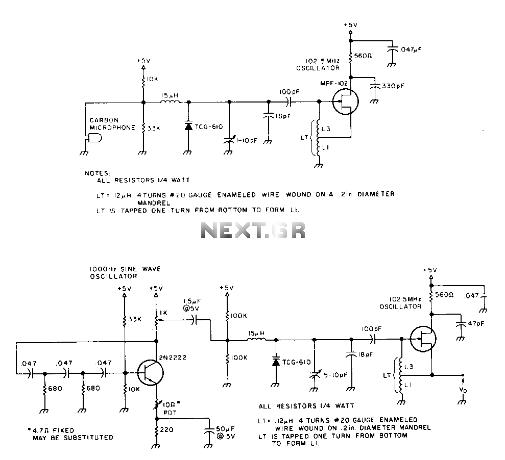
The 2N2222 circuitry is a three-element, phase-shift oscillator circuit designed to produce a 1,000 Hz sine wave. This sine wave is applied to the TCG-610 varactor diode, which has a capacitance of 6 pF at 4 V. This application...