
The L200 Datasheet an IC for Voltage and Current Programmable Regulation

The L200 is a versatile integrated circuit designed for various voltage regulation applications. The Programmable Voltage Regulator allows for adjustable output voltage levels, making it suitable for a wide range of electronic devices. The High Current Voltage Regulator is particularly notable for its short circuit protection feature, which safeguards the circuit and connected components from damage during fault conditions.
The Digitally Selected Regulator with Inhibit function provides an efficient means of controlling power delivery, allowing the circuit to be enabled or disabled based on digital signals. This feature is especially useful in battery-powered applications where power conservation is essential. The Programmable Voltage and Current Regulator offers dual functionality, enabling precise control over both voltage and current outputs, thus catering to applications requiring strict adherence to power specifications.
The High Current Regulator with NPN Pass Transistor configuration enhances current handling capabilities, making it ideal for high-demand applications. The High Current Tracking Regulator is designed to maintain consistent output voltage levels even as input voltage fluctuates, ensuring stable operation in varying conditions.
For applications requiring constant current delivery, the Constant Current Battery Charger is an excellent choice, providing reliable charging for rechargeable batteries without overcharging risks. The Light Controller enables automated control of lighting systems, enhancing energy efficiency and user convenience. Lastly, the 30 W Motor Speed Control circuit allows for precise regulation of motor speeds, suitable for various industrial and consumer applications.
Each of these circuits can be further explored in the datasheet, which provides detailed schematics, component values, and operational guidelines to aid in implementation and design.In the datasheet, you will see the L200 application circuits diagrams such as Programmable Voltage Regulator, High Current Voltage Regulator with Short Circuit Protection, Digitally Selected Regulator with Inhibit, Programmable Voltage and Current Regulator (click to enlarge figure above), High Current Regulator with NPN Pass Transistor, High Current Tracking Regualtor, Constant Current Battery Charger, Light Controller, and 30 W Motor Speed Control 🔗 External reference
Related Circuits
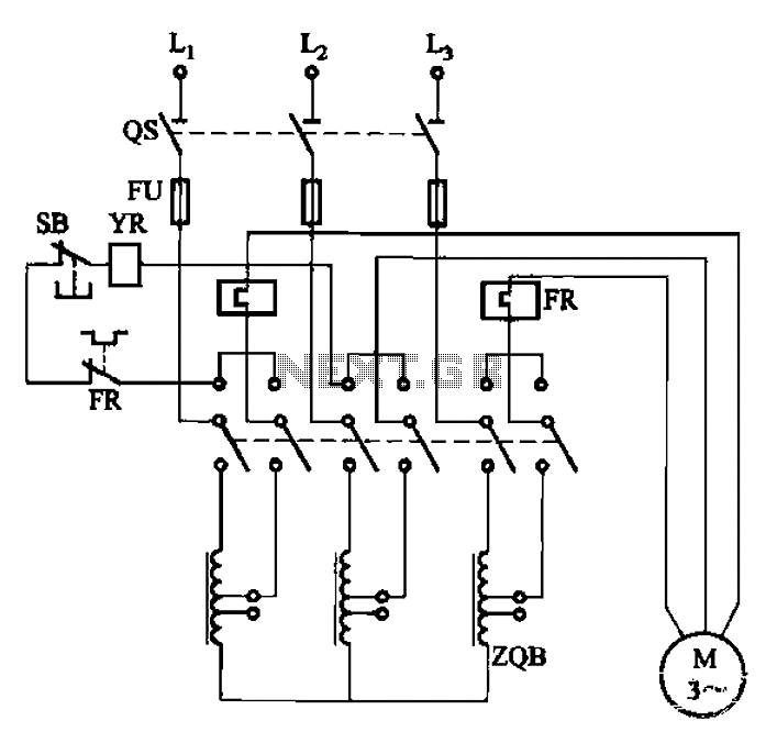
The circuit illustrated in Figure 3-47 involves a three-phase AC motor that is initially connected through a step-down autotransformer. To initiate operation, the power switch is closed, and the operating handle is pushed to the start position. Once the...
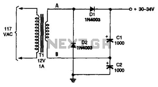
The voltage doubler consists of two diodes (D1 and D2) and two capacitors (C1 and C2), which are supplied by a 12-V, 1-A step-down transformer (T1). The voltage doubler circuit is designed to convert a lower input voltage into a...
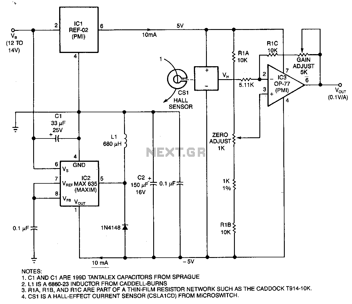
This circuit utilizes a Hall-effect sensor, comprised of an integrated circuit (IC) positioned within a small gap of a flux-collector toroid, to measure current in the range of 0 to 40 A. The current-carrying wire is threaded through the...
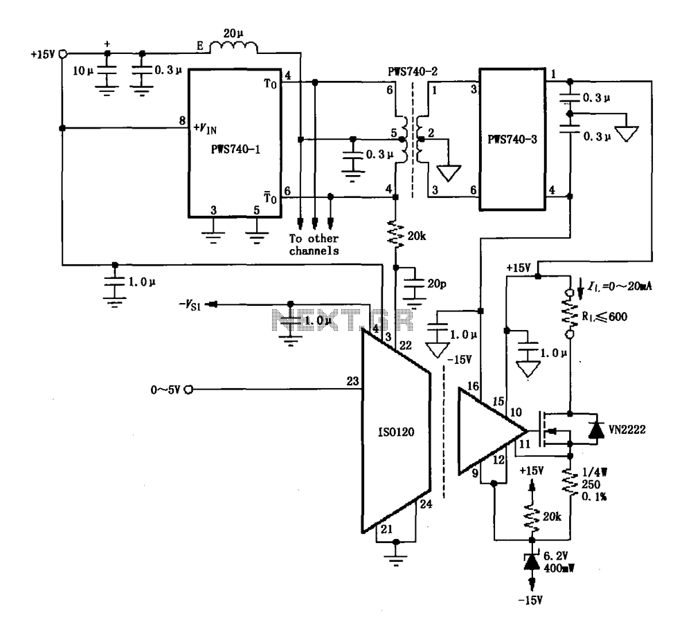
An eight-channel isolation circuit is constructed using the ISO120 and PWS740 components, designed for a 0 to 20 mA current loop. The figure illustrates only one channel, where the circuit converts a 0 to 5V input voltage into a...
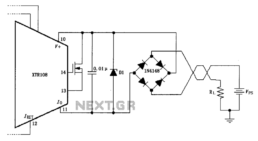
The circuit utilizes a Zener diode (D1) for overvoltage protection and a diode rectifier bridge for reverse voltage protection. The 1.4V drop across the diodes will result in a maximum voltage loss, meaning that the supply voltage (VPS) must...
A simple voltage probe circuit is depicted in the schematic diagram below. This circuit is highly useful for testing or troubleshooting discrete or integrated circuits. The simple voltage probe circuit serves as an essential tool for engineers and technicians engaged...