
Mini Audio Amplifier

The described low-watt audio amplifier employs an unconventional design approach by integrating a 1.8K ohm resistor at the output stage rather than the typical connection to the VCC (voltage common collector) line. This unique configuration can influence the amplifier's performance characteristics, particularly in terms of impedance matching and signal fidelity.
In this circuit, the output stage is designed to deliver approximately 250mW of power into an 8-ohm speaker, which is suitable for small audio applications such as personal speakers or compact sound systems. The choice of a low output power level indicates a focus on efficiency and minimal power consumption, making it ideal for battery-operated devices.
The resistor's placement at the output may serve multiple purposes, including limiting the output current, providing a level of feedback, or affecting the overall gain of the amplifier. This configuration could lead to a smoother frequency response and potentially reduce distortion, as the output stage interacts more directly with the load (the speaker) rather than being influenced by the power supply line.
For optimal performance, careful consideration of the amplifier's other components, such as transistors, capacitors, and additional resistors, is essential. These elements must be selected to ensure compatibility with the output stage design, maintaining the intended audio quality while achieving the desired power output. The overall circuit should be designed with attention to thermal management, as even low-watt amplifiers can generate heat under certain conditions.
In summary, this low-watt audio amplifier showcases an innovative design choice with its output resistor configuration, aiming to deliver efficient power to small speakers while maintaining audio integrity.This is a low watt audio amplifier with a different technique in design. The 1.8K resistor has been connected to output of the circuit instead of VCC line. The output power of the circuit is about 250mW on an 8 ohms small speaker. 🔗 External reference
Related Circuits
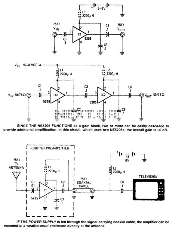
Except for the coupling and decoupling capacitors, IC1 is a complete wideband amplifier that has a fixed gain of 20 dB up to 450 MHz. No external compensation is required. Since the NE5205 functions as a gain block, two...
This is a straightforward, cost-effective Hi-Fi quality power amplifier. It can be constructed in five different configurations, as indicated in the table, ranging from 20 W to 80 W RMS. This Hi-Fi quality power amplifier is designed to deliver high...
A 30W Class AB power amplifier circuit diagram utilizes a power transistor. To set up the amplifier, adjust the variable resistor R1 to its maximum value and R12 to zero. After completing this setup, activate the amplifier. Adjust R1...
This is a simple microphone preamplifier circuit which you can use between your microphone and stereo amplifier. This circuit amplifier microphone suitable for use with normal home stereo amplifier line/CD/aux/tape inputs. This microphone preamplifier can take both dynamic and...
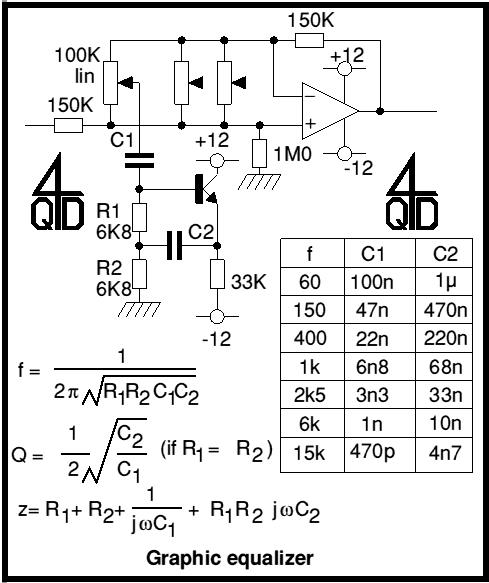
Audio graphic equalizers are very common as commercial products (for Hi-fi, car audio and stage use) but circuits for them are very rarely published. I didn't design this one but it's really very simple. The details shown are...
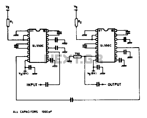
A wideband high gain configuration using two SL550s connected in series. The first stage is connected in a common emitter configuration, while the second stage is a common base circuit. Stable gains of up to 65 dB can be...