
Opamp Filters schematics

More: First order low or high pass cutoff frequency (-3dB point) = 1/(2pi*R*C)
2nd order low or high pass cutoff frequency (-3dB point) = 1/2pi(R1*R2*C1*C2)^0.5
Example for 200 Hz cutoff frequency - R1=R2=7.95K, C1=C2=0.1uF
The description outlines the application of operational amplifiers (opamps) in the design of active second-order filters, specifically low pass, high pass, and bandpass configurations. Each filter type serves distinct purposes in signal processing by allowing certain frequency ranges to pass while attenuating others.
In the case of the low pass filter, it permits signals with frequencies below the cutoff frequency to pass through while attenuating those above it. Conversely, the high pass filter allows signals above the cutoff frequency to pass, attenuating those below. The bandpass filter combines the characteristics of both, allowing a specific band of frequencies to pass while attenuating frequencies outside this range.
The performance of these filters is characterized by their roll-off rate, which is 12 dB per octave. This means that for every doubling or halving of frequency outside the passband, the output voltage amplitude decreases to one-quarter of its previous value. This property is crucial in applications requiring precise frequency selection or rejection.
The cutoff frequency, or -3 dB point, for first-order filters is calculated using the formula \( f_c = \frac{1}{2\pi RC} \), where R is the resistance and C is the capacitance. For second-order filters, the cutoff frequency is determined by the formula \( f_c = \frac{1}{2\pi\sqrt{R_1 R_2 C_1 C_2}} \).
In the provided example with a desired cutoff frequency of 200 Hz, selecting resistor values \( R_1 \) and \( R_2 \) as 7.95 kΩ and capacitor values \( C_1 \) and \( C_2 \) as 0.1 µF ensures that the filter will effectively operate at the specified frequency. This design methodology is essential for engineers tasked with developing circuits that require specific frequency response characteristics, such as audio processing, communication systems, and signal conditioning applications.The figures below illustrate using opamps as active 2nd order filters. Three 2nd order filters are shown, low pass, high pass, and bandpass. Each of these filters will attenuate frequencies outside their passband at a rate of 12dB per octave or 1/4 the voltage amplitude for each octave of frequency increase or decrease outside the passband. First order low or high pass cutoff frequency (-3dB point) = 1/(2pi*R*C) 2nd order low or high pass cutoff frequency (-3dB point) = 1/2pi(R1*R2*C1*C2)^.5 Example for 200 Hz cutoff frequency - R1=R2=7.95K, C1=C2=0.1uF 🔗 External reference
Related Circuits
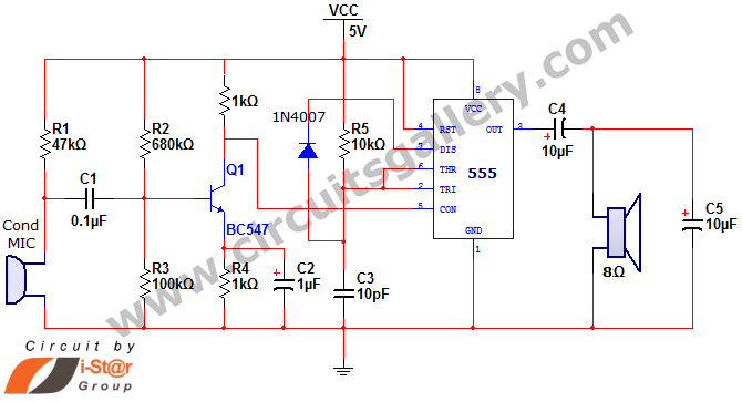
This document discusses a simple project utilizing the 555 timer IC. The 555 timer IC can be configured as an audio amplifier using an astable multivibrator configuration. It performs pulse width modulation (PWM) on an audio signal. The current...
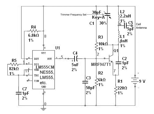
The circuit is based on the NE555 timer, functioning as a simple noise maker, with its output connected to a single transistor oscillator. This oscillator is designed to operate within a frequency range of 800 MHz to 2 GHz,...
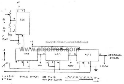
This circuit is designed to provide long time delays using the integrated circuit Timer 555. It utilizes the NE555 to generate pulse frequencies, which are then divided by a 4017 decade counter to achieve the desired delay. The component...
The Up Alarm is designed to provide an audible alert when sunlight is detected or when a light source is activated in a dark environment. It can also be utilized to sense various light sources such as beams or...
The power supply is integrated into the base of the microphone, which may cause hum issues, even with the onboard potentiometer designed to nullify this effect. Consequently, the microphone features two cables: one for power and another for audio...
Here they exist two regulator circuits, that use the IC L200, as regulator of voltage and current, the company SGS-Thomson, which give these circuits. In circuit Fig.1, we can regulate the output voltage, with the RV1, while in the...