
Opamp Wien-bridge oscillator

The Wien-bridge oscillator is a type of electronic oscillator that generates sine waves. It employs a specific arrangement of resistors and capacitors to establish the frequency of oscillation. The core of the circuit is an operational amplifier configured in a non-inverting mode, which provides the necessary amplification for the oscillations to sustain.
In the basic configuration, the Wien-bridge oscillator includes two resistors (R1 and R2) and two capacitors (C1 and C2) arranged in a bridge circuit. The resistors and capacitors are selected such that they set the frequency of oscillation according to the formula:
\[ f = \frac{1}{2\pi R \sqrt{C1 \cdot C2}} \]
where R is the resistance value chosen for R1 and R2. The gain of the operational amplifier is determined by the ratio of R2 to R1, which must be greater than three for stable oscillation. This gain condition ensures that the feedback network provides the right amount of positive feedback to sustain oscillations.
To maintain stable oscillations and prevent saturation of the operational amplifier, a light bulb or thermistor is often used as a variable resistor in the feedback loop. This component adjusts the gain dynamically, allowing the oscillator to stabilize at the desired amplitude.
The output of the Wien-bridge oscillator is a sine wave, which can be utilized in various applications, including signal generators, audio applications, and testing equipment. The design's simplicity and effectiveness make it a popular choice in both educational and professional settings for generating high-quality sine waves.The Wien-bridge oscillator, consists of an Operational Amplifier (OA) in a non-inverting configuration with gain 1 + R2/R1 and a RC feedback network.. 🔗 External reference
Related Circuits
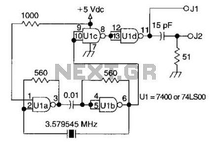
A circuit utilizing one 7400 TTL can operate with fundamental type crystals ranging from 1 to approximately 13 MHz. The output is rich in harmonics, making this oscillator suitable for calibration and testing applications. The circuit in question employs a...
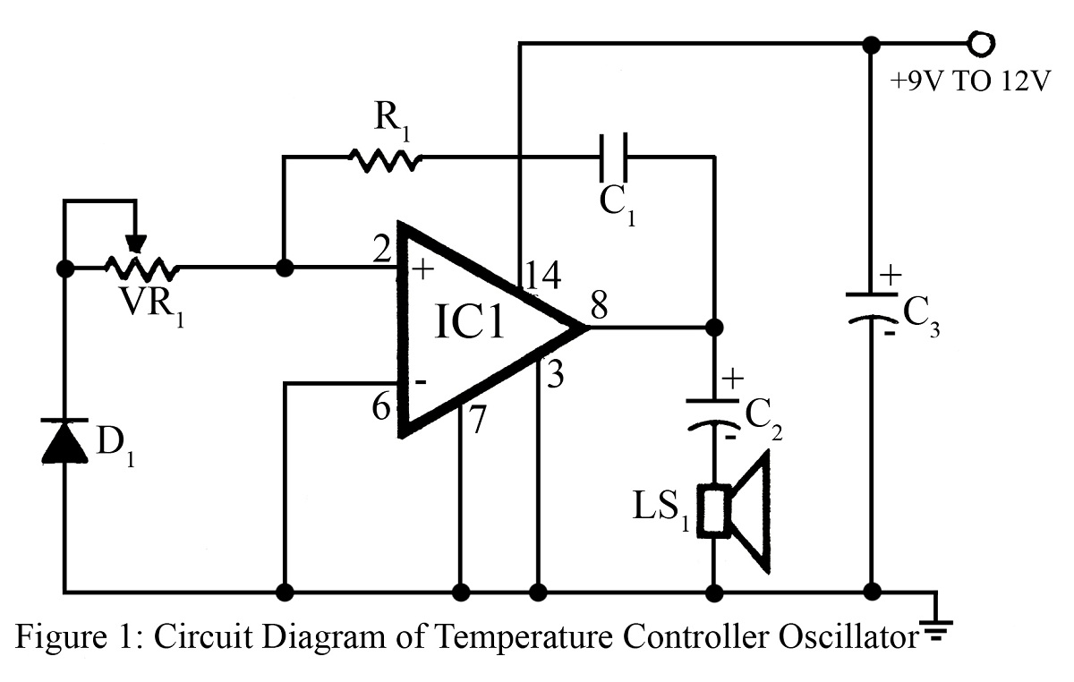
The output frequency or tone of this oscillator circuit varies with the temperature at which the input germanium diode is maintained. The reverse resistance of D1 ranges from 500 ohms to 10 k ohms when the temperature fluctuates between...
The RF design and construction of radio frequency oscillators. Radio frequency (RF) oscillators are essential components in various electronic systems, generating signals at specific frequencies used for communication, signal processing, and other applications. The design of RF oscillators involves several...
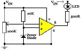
A simple voltage status monitor built around the LM741 operational amplifier. These circuits are recognized for their accuracy, ease of operation, and cost-effectiveness. The LM741 serves as an operational amplifier, widely used for various applications. The primary function of...
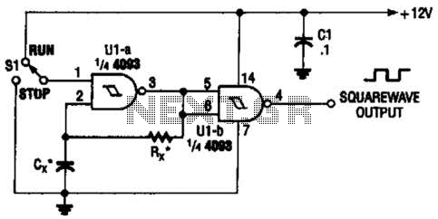
Two gates of the Quad 4093 are utilized to create an oscillator. The resistor (R) can range from approximately 5 kΩ to around 10 kΩ. The capacitor (Cx) can vary from about 10 pF to higher values, with the...
This receiver is MC3371. Pin 16 is the RF input to the mixer and pin 1 and pin 2 is the local oscillator. The product comes out at pin 3. Imagine you want to receive at 100MHz. The local...