
Open doors and windows automatic laser beam control circuit

The described circuit T employs a laser diode LED as a primary light source, functioning effectively as both a laser and a light-emitting diode. The inclusion of a resistor (R) and a protection diode (VD) is crucial for safeguarding the laser diode from current surges, which could otherwise damage the component. The multi-loop trimming potentiometer (RP) serves as an adjustable element, allowing users to fine-tune the sensitivity of the laser detection system according to specific requirements or environmental conditions.
In operation, when the laser beam is directed towards the phototransistor (VT), it triggers conduction in the device. This conduction results in a zero base potential at VT3, indicating that the phototransistor is effectively responding to the laser light. The emitter of VT3 also reaches a zero potential, which is then fed into the first gate of the CD4001 integrated circuit. The logic gate interprets this zero potential as a high output signal.
The high output from the CD4001 is pivotal for the subsequent operation of the circuit. It facilitates the conduction of transistor VT4, which is connected in such a way that it can amplify the output signal. The conduction of VT4 leads to the activation of a green LED, providing a visual indication of the system's readiness or standby state. This feature enhances user interaction by signaling that the circuit is operational and awaiting further input.
Overall, Circuit T exemplifies a well-designed electronic system that integrates a laser diode, phototransistor, and logic gate to create a responsive light detection mechanism. The careful selection of components and the inclusion of protective measures ensure reliability and functionality in various applications. Circuit T as principle: In this circuit, a laser diode LED, as a light hair emitter, in addition to other properties may also be used similar light emitter laser diode substitu tion pipe. Resistor R. And diode VD, as the laser diode current protection circuit, multi- loop trimming potentiometer RP, for adjusting the sensitivity of the laser. Under normal circumstances, when a laser beam is irradiated to a phototransistor VT. When on, VTz conduction, VT3 base potential is zero (VL zero bias), VT3 deadline, its emitter potential is zero.
The zero potential applied to the IC. (CD4001) first gate N, the input of the results of N. The output is high. But also through the high resistance of the transistor VT4 added to the base so that VT4 conduction, so that the green LED, lights up. In this case the circuit is in a standby state waiting.
Related Circuits

This article explains how to construct a general-purpose DTMF decoder using an affordable chip from MITEL. The circuit supports DTMF squelch based on a three-digit station ID (covering all 999 combinations). It can also decode four additional commands, which...
This article presents a high reliability 1200V High Voltage Integrated Circuit (1200V HVIC) for half bridge driver applications, aimed at reducing the IC's supply current by approximately 50%. The 1200V High Voltage Integrated Circuit (HVIC) is designed specifically for half-bridge...
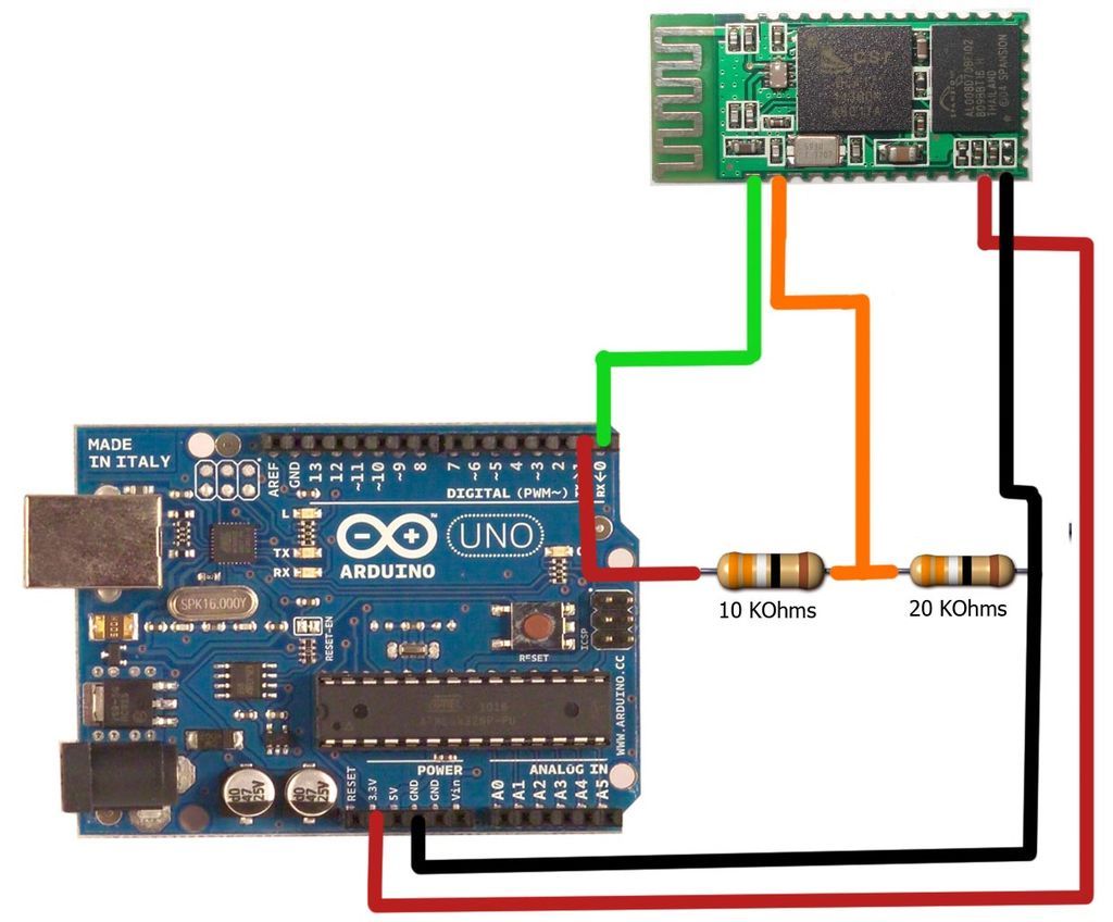
The motion games on the Nokia 5800 sparked an interest in creating a real-world version of a racing car controlled by tilting a phone. The motion-controlled robot, named Hercules due to its high torque and speed, is operated via...
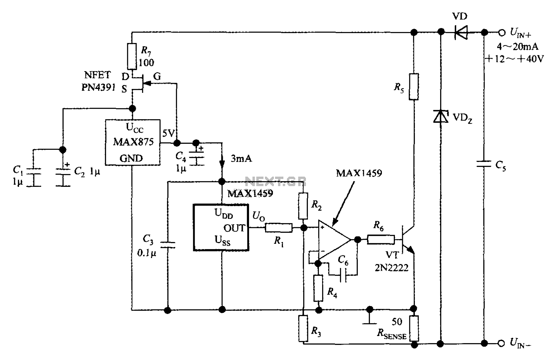
A 4 to 20 mA current transmitter circuit is implemented using the MAX1459, as illustrated in the accompanying figure. The output voltage from the programmable gain amplifier (PGA) is supplied to a spare amplifier chip, and subsequently, an external...

Several schematic drawings of battery charger circuits are provided. These circuits cover 5W to 200W for NiCd, NiMH, Lead-Acid, Li-Ion/Polymer, and LiFePO4 battery packs. The charger circuit files aim to assist users in selecting the appropriate chargers and to...
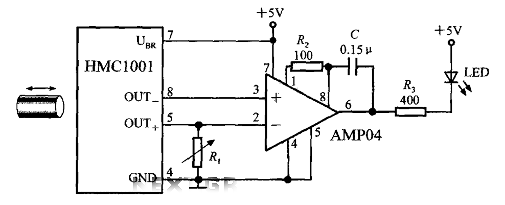
The circuit depicted in the figure includes the HMC1001 magnetic sensor, an operational amplifier (AMP04), and a light-emitting diode (LED), forming a proximity switch circuit. In this application, the operational amplifier functions as a comparator. When a magnet, approximately...