
dtmf circuit

The DTMF decoder circuit primarily utilizes the MT8870 chip, which plays a crucial role in decoding the dual-tone multi-frequency signals. The design includes an input stage where the incoming audio signals are filtered and amplified to ensure they meet the required signal levels for the decoder. The switched capacitor filter technology employed in the MT8870 allows for precise frequency selection, enabling the decoder to differentiate between the various DTMF tones effectively.
The external components, such as capacitors and resistors, are selected to set the timing and filtering characteristics of the circuit, ensuring optimal performance under various signal conditions. For instance, the values of C2, R11, and R12 are critical in determining the response time and stability of the DTMF detection. The addition of the expansion port facilitates future enhancements to the circuit, allowing for integration with other systems or the addition of new features as technology evolves.
In terms of layout, the circuit should be designed to minimize noise and interference, which can adversely affect DTMF detection accuracy. Proper grounding techniques and the use of shielded cables for the input signal can help mitigate these issues. Furthermore, the implementation of audio equalization techniques can enhance the decoder's ability to handle TWIST and TALKOFF, ensuring reliable operation even in less-than-ideal conditions.
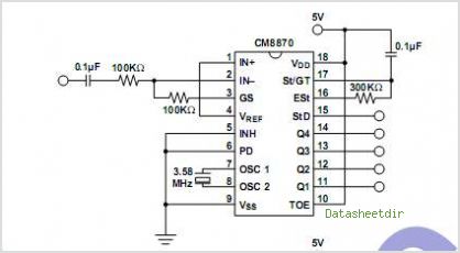
Overall, this DTMF decoder circuit offers a versatile solution for applications requiring remote control capabilities, leveraging the advanced features of the MT8870 chip to achieve reliable signal decoding and command execution.This article describes how to build a general purpose DTMF decoder with a low-price chip from MITEL. The circuit supports DTMF squelch based on 3 digits station ID (full 999 combination). It also supports decoding of 4 additional commands - station ID plus one more digit which can be used to perform remote control on external devices (on/off or si ngle shoot trigger operation ). One expansion port is included to provide future development. Core of the whole equipment is the MT8870 DTMF decoder. This is a state of art single chip DTMF receiver incorporating "switched capacitor filter" technology and advanced digital counting / averaging algorithm for period measurement. Conventional method of frequency decoding usually based on frequency counting or phase locking technique.
These methods are time consuming and inaccurate when handling unsteady complex signal. Switched capacitor filter technology based on a completely different approach. It works on the theory that any A. C. signal are rapid changes of potential energy with repect to specific time factor. A. C. components, provided that they bear the same frequency characteristic, will have the same timing on instantaneous potential variation. For example, a signal of frequency 1 Hz will experience peak positive value every one second. - the duration of 1 sec. will be constant among any A. C. signal bearing frequency 1 Hz, even though they have different wave forms. Suppose a circuit is designed to sample the potential value of a signal at preset intervals ( say, at exactly 90 degree phase shift timing for a specific frequency ).
If the total sum of all samples always experience zero while signal really present. We can conclude that an A. C. component of that specific frequency has been identified. Each fixed timing will be good for only one frequency. Since DTMF is a combination of 4 row tones and 4 column tones, it will need at least 8 sets of such time switching circuits. In the real world, there are more then 8 sets of such circuits in order to handle tolerance in the incoming DTMF signal while decoding result is developed on an averaging of outputs from all these filters.
TWIST is the failure of decoding a valid DTMF signal due to non-linear frequency response of a transmission media. Among the two enemies, TWIST is easier to deal with since it can be controlled by audio equalization on the whole transmission path.
These equalization can be done internally inside the DTMF decoding chip or externally via additional audio filters. According to factory specification, MT8870 can stand TWIST tolerance of +/- 6db. That is quite sufficient to compensate pre-emphasize and de-emphasize distortion caused by FM media. This should not be a problem unless the transmission is highly distorted. TALKOFF is the wrong recognition of DTMF component in human voice as true DTMF signal. This is an unavoidable factor since human voice always contain valid DTMF combination. Fortunately, presence of these valid DTMF components are unsteady. Unlike real DTMF generated from a touch-tone keyboard, these `human` DTMF cannot maintain on a constant combination.
So they can be isolated by DELAY discrimination. If a decoded DTMF signal can stay on constantly for certain duration which exceed those normal period experienced in human voice, then it can be identified as a real DTMF command. By looking at the schematic circuit, there are some external components hooked to MT8870 ( C2, R11, R12, D9 ).
Pin 16 of MT8870 is EST (Early Steering) output. It will flag logic high whenever DTMF combination is detected in the input signal ( including TALKOFF error detection ). Pin 17 is GT (guard time) control, it is a trigger type input. The level on pin 17 is arranged as a delayed EST via C7 and R12. If the detection of DTMF is long enough for voltage at pin 17 to build up with time, it can be considered as a valid DTMF signal.
The STD output line (pin 10) 🔗 External reference
Related Circuits
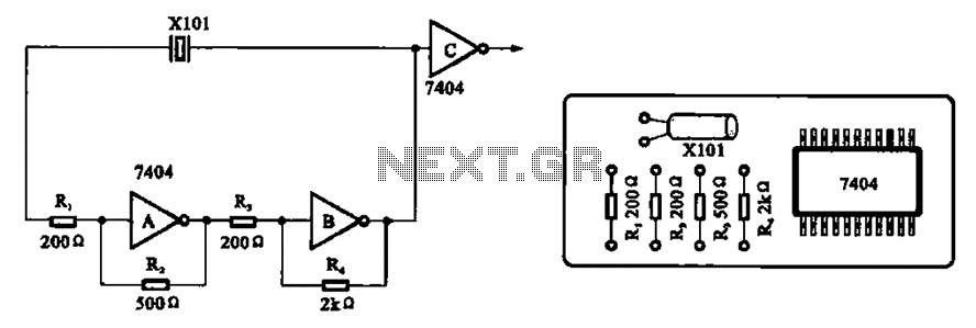
A clock oscillator is commonly utilized in digital signal processing circuits and microprocessor circuits. Digital signal transmission and signal processors necessitate a clock, which serves as the system's timing signal, while the data signal functions as a synchronization signal....
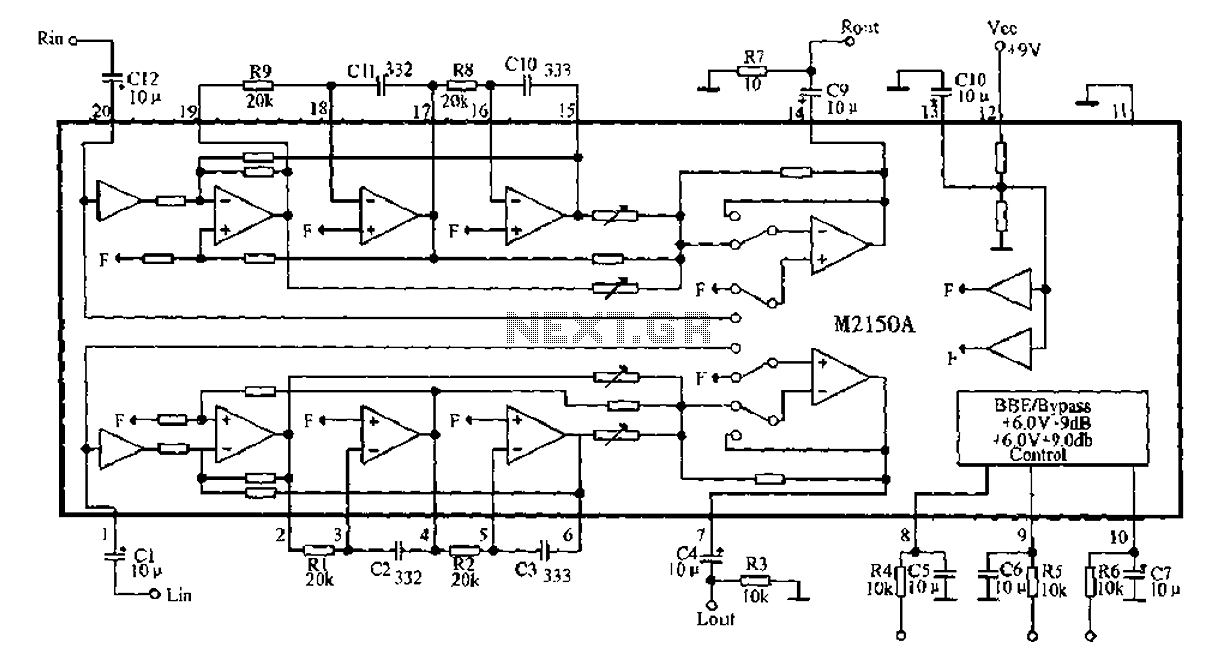
4V flat monitor high voltage power supply circuit diagram. A wide range of 7 to 40V to 5V DC-DC step-down circuit diagram. Light control switch circuit diagram for safety. Circuit 555 constitutes a control circuit diagram for photoelectric applications. The...
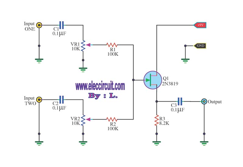
This circuit is a simple mixer circuit that can mix two signal channels into one output channel. It utilizes a codec circuit to convert stereo audio into mono audio. The circuit can also increase the number of channels by...
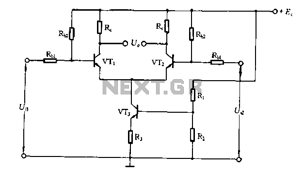
The differential amplifier circuit features a constant current source. The differential amplifier is a fundamental building block in analog electronics, utilized for amplifying the difference between two input voltages while rejecting any signals that are common to both inputs. Central...
The CAMD CM8888 8888-2 is a fully integrated DTMF transceiver that features adjustable guard time, automatic tone burst mode, call progress mode, and a fully compatible interface for 8051 and 8086/8 microprocessors. It is manufactured using advanced CMOS technology,...
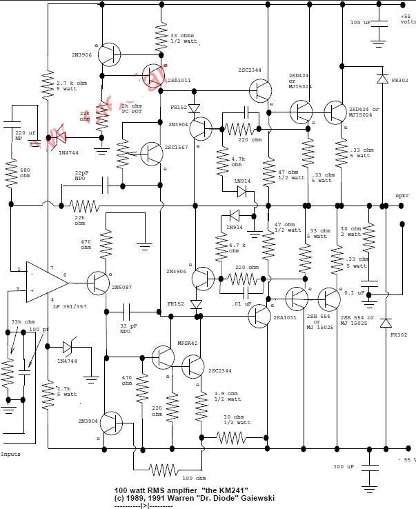
This is a 100-watt basic power amplifier designed to be relatively easy to build at a reasonable cost. It offers better performance, or musical quality, than the standard STK module amplifiers commonly found in mass-market stereo receivers. The design...