
Open Source Project for Tesla/Jackson Wireless Transmission

The described circuit operates at a frequency of approximately 50 kHz, facilitating the transfer of energy through inductive coupling between a transmitter and receiver coil. The system's performance is influenced by several parameters, including grounding techniques, coupling distance, and the physical arrangement of components. The use of a metal plate as a receiver ground enhances the inductive coupling, while the removal of the recovery battery simplifies the circuit and eliminates potential interference.
The circuit's design allows for experimentation with different configurations to optimize energy transfer. Adjustments to the number of turns in the coils and the wire gauge can be made to achieve the desired resonance and efficiency. The presence of high voltage at the receiver, particularly the risk of exceeding 50 volts without load, necessitates careful consideration of capacitor usage to prevent component damage.
The output waveform characteristics are critical for effective energy rectification and storage. The suggestion to utilize U-shaped magnetized transformer cores or a steel core transformer aligns with the need for efficient energy conversion. The anticipation of a sine wave output when the system reaches resonance indicates a shift towards a more stable and usable output, contrasting with the current irregular waveforms.
Implementing an ultra-fast recovery full-wave bridge rectifier is advisable for effective energy storage, particularly given the pulsing nature of the output. The exploration of three-phase configurations may further enhance the circuit's performance, potentially allowing for higher frequencies and improved energy transfer efficiency. Overall, the circuit presents a complex interplay of inductive coupling, resonance, and waveform management, requiring careful tuning and configuration to maximize effectiveness.At around 50 Khz i can get over 40 volts at the receiver. Light`s LED`s no probs. It even blew a 5mm LED. The cap I had on the AC was blocking the energy. Anyway what I did was connect the primary negative to ground with the secondary on the transmitter, a "real" ground, then the receiver I use the metal plate layed on the concrete, the LED is the same brightness even if the receiver ground is connected to the transmitter ground or not, must be what he say`s is an inductive relationship with the ground ( same thing that ruins batteries if they are left on the ground). And I removed the recovery battery. Neons light from the toroids no problem now. Under load with 1 x 5mm LED ( that`s the only LED I have left ) the transmitter toroid reads 2. 5 volts AC and the voltage across the LED is 2. 94 volts. Which seems like good transfer considering they do not share a ground connection and 50 Ma @ 12 volts input.
Care must be taken when using caps on the receiver output because the voltage keeps rising to about 50 volts with no load, that`s how I blew the LED. On second thought I think the coupling distance on the primaries is just fine. As Nikola says these things can be adjusted for our own personal requirements, the coupling distance the number of turns the thickness of the wire the input voltage and many other things could be changed in differing cominations to acheive different effects.
Looking good! Looks to me that your still not in tune though. These coils are very sensitive once you get them in tune, just putting your hand by them will knock them out of tune and you will see the load drop off when you do. I suspect that your square wave is giving it enough of a ping to get it ringing a little bit and your receiver is picking up the HV field.
Try separating the coils at a greater distance like 5 or 10 meters and see if you can still get anything with the plate and/or ground wire. Distance effects the tuning slightly so you may need to make adjustments. Yeah I will need to use Mhz to get it into resonance. I can only play for now but I can learn some things. Putting my hand near it does afect the transfer but I have to get it within a few inch`s. I am using a square wave but it isn`t 50/50. Rectifying and storing the output is proving to be difficult. I have an idea from the testatika machine, U shaped magnetised transformer core`s or just a steel core transformer might work.
I guess when the transmitter is in resonance the receiver will output a sine wave so that will be much easier to use than the scratchy wave`s at the receiver now. An Ultra fast recovery FWBR might also help with storing the output. I am thinking my Bob Boyce transformer might be good to use on it if I construct a resonant AC tank with series inductors and caps.
It will idle with very low standby input and the output is kind of AC but I have it pulsing about 18 times at 2 us then a pause to the next group, could be worth a look for the fun of it I should maybe reconfigre the controller to three phase (three single pulses). This is what the waveform from the secondary of my transformer looks like. I can make it so there is no pause and all 2 us pulses with 2 us between, well I think I can. However if I reconfigure the controller to three phase I can tripple the effective frequency and hex it if the output is AC.
Anyway I have to cut MDF boards and paint the edge`s. But it is raining all weekend, looks like. I have to stoke the fire to dry the paint. 🔗 External reference
Related Circuits
In the production of LCD projectors, the primary factor threatening the lifespan of the LCD screen is the temperature generated by halogen lamps. The multi-function controller designed by this circuit is highly effective for protecting liquid crystal projectors. The...
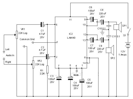
The LA4440 audio amplifier IC can be utilized to design a straightforward stereo power audio amplifier project, capable of delivering 6 watts of output power into an 8-ohm load. This audio amplifier IC features a minimal number of external...
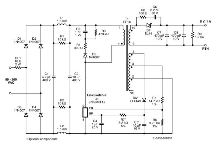
A very simple 5-volt constant voltage, constant current (CV/CC) universal-input power supply for cell phone or similar charger applications can be designed using the LNK616PG product from the LinkSwitch-II family. This low-cost charger adapter accepts a wide range of...
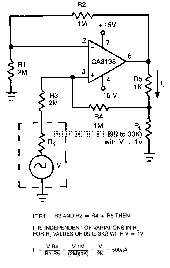
This circuit employs a CA3193 precision operational amplifier to provide a current that remains consistent regardless of variations in the load resistance (RL). By configuring the input resistance (RI) to be equal to resistance R3 and setting resistance R2...
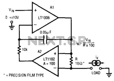
This circuit is a programmable current source that utilizes the LT1102 operational amplifier from Linear Technology Corp. in conjunction with the LT1006 operational amplifier. The first amplifier (A1), biased by a voltage source, drives current through a resistor (R)...
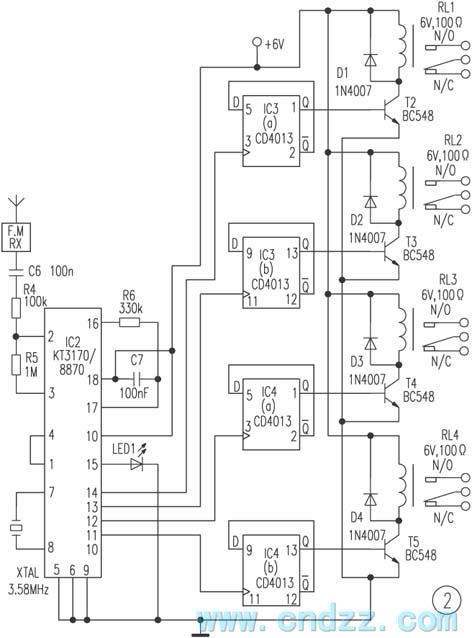
The remote control transmitter consists of a DTMF generator and an FM transmitter circuit. A UM91214B phone-specific integrated circuit (IC) is utilized to generate the DTMF signal, with a 3V power supply provided by a 3V zener diode (D1)....