
Operational Amplifier (Op-Amp) Oscillator
 Oscillator")
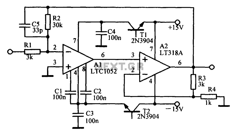
The operational amplifier oscillator circuit is designed to generate a periodic waveform output, typically a sine or square wave, using the properties of feedback and amplification inherent in op-amps. This configuration can be particularly advantageous in applications requiring low-frequency signals, such as audio applications or low-frequency signal processing.
The basic architecture of an op-amp oscillator generally involves a feedback network that determines the frequency of oscillation. Common configurations include the Wien bridge oscillator and the phase shift oscillator. In the Wien bridge oscillator, resistors and capacitors are arranged in a bridge configuration to set the frequency, while a variable resistor can be used to stabilize oscillation amplitude. The phase shift oscillator, on the other hand, utilizes a series of resistors and capacitors to create a total phase shift of 180 degrees, complemented by the 180-degree phase shift provided by the op-amp itself.
In addition to the frequency-determining components, the circuit typically includes a power supply to provide the necessary voltage levels for the op-amp operation. The stability and accuracy of the output waveform can be influenced by component tolerances, temperature variations, and power supply fluctuations, necessitating careful selection and design of the components used in the circuit.
Overall, the operational amplifier oscillator circuit is a versatile and effective solution for generating low-frequency signals, making it a valuable tool in various electronic applications.This is Operational an Amplifier (Op-Amp) Oscillator circuit. This circuit has some advantages, they are this circuit can be operated at low frequencies with. 🔗 External reference
Related Circuits

The AD8555 is a zero-drift sensor signal amplifier featuring digitally programmable gain and output offset. It is designed to effectively and accurately convert variable pressure sensor and strain bridge outputs into a well-defined output voltage range. Additionally, the AD8555...
Amplifying circuit diagram to enhance the output current and voltage. An amplifying circuit is designed to increase the amplitude of an input signal, resulting in a higher output current and voltage. This type of circuit is commonly utilized in various...
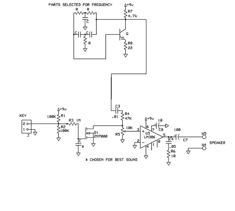
A schematic for a code practice oscillator is needed, which can be connected to a keyer. The desired setup involves using a Picokeyer, allowing the oscillator to be plugged into the key jack of the Picokeyer. The output should...

The LM4610 is a DC-controlled tone (bass/treble), volume, and balance circuit designed for stereo applications in car radios, televisions, and audio systems. It also incorporates National's 3D-Sound circuitry, which can be adjusted externally using a simple RC network. An...
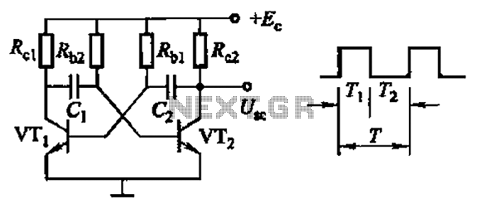
Common non-sinusoidal oscillator circuit, waveform and frequency formula - square wave oscillator - self-excited multivibrator The common non-sinusoidal oscillator circuit, specifically the square wave oscillator, is a fundamental electronic circuit utilized to generate square wave signals. It operates based on...
This circuit was designed and manufactured in the 1980s. Since then, it has operated without issues. There are no specific construction challenges, aside from the usual considerations: attention to the power supply requirements, selection of an appropriate heatsink, and...