
Operational Amplifiers circuits

The Wien-Bridge oscillator is a well-established circuit used for generating sine waves, characterized by its simplicity and effectiveness. The oscillator’s architecture typically includes resistors and capacitors arranged to provide the necessary phase shifts. The low-pass and high-pass filters serve to shape the frequency response, ensuring that only the desired frequencies are amplified and sustained in oscillation. The feedback mechanism is critical, as it stabilizes the amplitude of the oscillation and ensures consistent output.
In the second stage, the Schmitt Trigger is an essential component for converting the sine wave output of the Wien-Bridge oscillator into a square wave. The Schmitt Trigger employs hysteresis, which provides a clear threshold for switching states, resulting in a clean transition from low to high states without the noise that can occur in less robust designs. This characteristic is particularly advantageous in digital applications where signal integrity is paramount.
The addition of a resistor in parallel with the capacitor in the feedback loop of the Schmitt Trigger serves multiple purposes. It mitigates any potential output offset voltage, which can distort the waveform, and it creates a virtual ground that stabilizes the operational amplifier's input. The high input impedance of the 741 operational amplifier is a significant feature, allowing it to interface with high-impedance sources without loading them down, thus preserving the integrity of the input signal.
The gain of the circuit can be finely tuned by adjusting the ratios of the resistors, allowing for versatile applications across various frequency ranges. This adjustability, combined with the ability to generate different waveforms—such as sine, square, and sawtooth—makes the 741 operational amplifier an invaluable tool in signal processing and function generation applications. By experimenting with different component values and configurations, engineers can tailor the output to meet specific requirements, enhancing the circuit's functionality in a range of electronic projects.The Wien-Bridge oscillator fulfills these requirements because there is a low pass filter, a high pass filter and a 180 deg. phase shift from the feedback networks from the input to output. This totals 360 deg. to start the circuit oscillating. If all three of the criteria are met and you have a resonant Grequency under 1 MHz, then you have a cir
cuit that produces a Sine Wave from a DC power source. The second stage of our Function Generator is this Schmitt Trigger. This circuit is used to convert a Sine Wave into a Square Wave. This happens because the input signal is large enough to pass through both the lower and the upper voltage trip points. This is possible when the upper part of the Sine Wave hits the output voltage. The voltage will go directly to +Vsat and stay there until the lower peak causes it to go to -Vsat add infinitum.
This circuit produces a "ramp" voltage. Normally you would have just a capacitor in the negative feedback loop. But because we want no output offset voltage, we had to put a resistor in parallel with the cap. Besides limiting the output offset, it produces our "Virtual Ground. " This virtual ground is created by the 741`s very high input impedance. About 150 M*`s of it. What happens is the input resistor is connected to the positive input and a resistor coming from the output signal is connected also to the +in. Total current will go through the first resistor and split towards the second resistor because it`s an easier path to ground.
When this is set up like this, as long as both resistors are less than 150 Megs, a ratio situation occurs between them. Depending on the ratio, or Gain created, you can control how much amplification it has. Now throe in the cap and a Saw Tooth wave shape is created. In conclusion, the 741 Op Amp can be used in a variety of ways to produce many different outputs. It does this by having many diverse methods of installation. By playing with component values and connections, you can create and manipulate any desired AC output signals.
🔗 External reference
Related Circuits
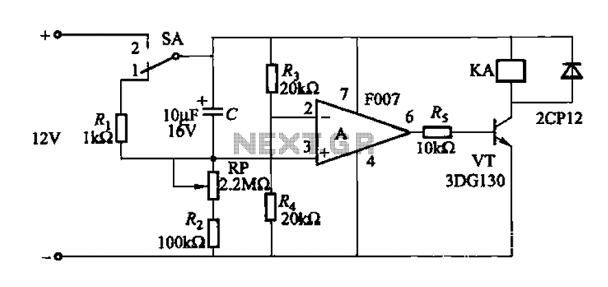
A delay circuit utilizing an operational amplifier functions as a comparator, providing high timing accuracy. The timer's delay range is from 1 to 30 seconds. The delay time is determined by resistors Ri, RP, and capacitor C. By adjusting...
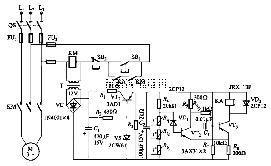
A P-type transistor (VT2, VT3) and other components form a common emitter-coupled trigger, functioning as a Schmitt trigger device. This setup serves as a switching circuit to detect changes in the resistance of a PTC thermistor, thereby controlling the...
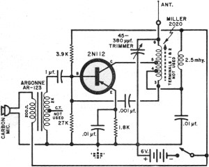
It had been a little over a decade since the invention of the transistor when this article appeared in the August 1959 edition of Popular Electronics. Transistors were still a mystery to many, including engineers, technicians, and hobbyists. Author...
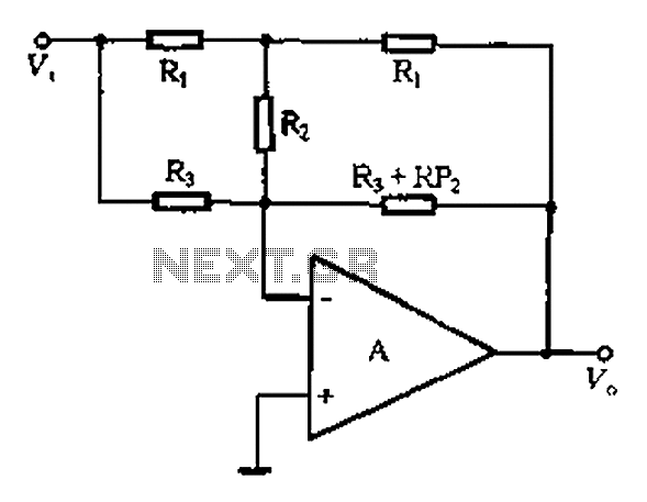
At high frequencies, the capacitor Cz can be considered a short circuit (i.e., the resistance of the RPi is negligible). This is illustrated in Figure 4-6 (a) of the apparatus, which corresponds to the equivalent circuit shown in Figure...
The fundamental issue presented is the perception that logic gates in a circuit seem to generate power from nothing, which contradicts the principles of physics. For instance, consider two NOT gates connected in series. It appears that the first...
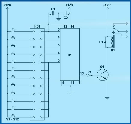
Circuit diagram schematics of electronic keys, electronic locks, digital electronic locks, transistor code locks, and combination electronic locks. The circuit schematics for electronic locking mechanisms encompass a variety of designs tailored to enhance security and convenience in access control systems....