
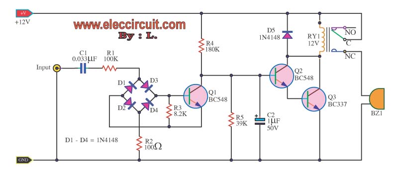
A delay circuit using an operational amplifier

The delay circuit described employs an operational amplifier (op-amp) configured as a comparator to achieve precise timing functions. The operational amplifier is an essential component in this circuit, as it amplifies the difference between two input voltages and switches its output state based on the comparison.
The timing mechanism operates within a specified range of 1 to 30 seconds, making it suitable for various applications requiring controlled delays. The delay time is primarily influenced by the resistors Ri and RP, along with the capacitor C. The resistor Ri is typically a fixed resistor, while RP is a variable resistor (potentiometer) that allows for fine-tuning of the delay period.
In operation, when the circuit is powered, the capacitor C begins to charge through the resistors Ri and RP. The charging time of the capacitor determines the delay period before the output of the op-amp changes state. The relationship between the resistance values and the capacitance can be described by the time constant formula τ = R × C, where τ is the time constant, R is the equivalent resistance seen by the capacitor, and C is the capacitance. In this circuit, the effective resistance is a combination of Ri and RP.
Adjusting the potentiometer RP alters the resistance in the timing circuit, thereby modifying the time constant and, consequently, the delay time. This feature allows for versatile applications, enabling the user to set specific timing intervals as required.
To implement this circuit, it is crucial to select appropriate values for Ri, RP, and C to ensure that the desired timing range is achieved while maintaining stability and accuracy. Additionally, the op-amp should be chosen based on its specifications, such as bandwidth and power supply requirements, to ensure optimal performance in the delay circuit.
Overall, this delay circuit is a robust solution for applications that necessitate precise timing control, leveraging the capabilities of operational amplifiers for reliable performance.A delay circuit using an operational amplifier It uses an operational amplifier A as a comparator, high timing accuracy. The timing of the timer is in the range of 1 ~ 30s. Del ay time is determined by Ri, RP and C, adjust RP, can change the delay time.
Related Circuits
This circuit displays a sound generator that simulates the siren of a British police car. The circuit is constructed using two timer IC 555. The sound generator circuit designed to simulate a British police car siren utilizes two 555 timer...
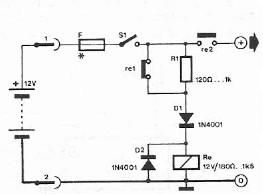
Safety polarity connection circuit design using common electronic components The safety polarity connection circuit is designed to ensure that electronic devices are connected with the correct polarity, preventing damage from reversed connections. This circuit typically employs common electronic components such...
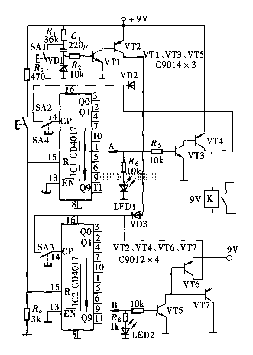
The circuit consists of a two and four decimal counter CD4017 used in conjunction with a password switch. It is composed of the output terminals from the key switch logic combination of components, which provide another feature of the...
This application note demonstrates a simple 8-direction digital compass application utilizing Zilog's Z8 Encore!® MCU and an external compass sensor hardware. Communication ports are provided for the digital compass to receive commands and send status via the I2C bus...
The telephone repeater is a circuit designed to amplify the call signal, making it louder than the original. This circuit has been developed in response to specific requests. The telephone repeater circuit functions by receiving the incoming audio signal from...
The function of the sound level display circuit is to enhance the appearance of an amplifier circuit or a radio player. It provides an impressive visual representation of audio levels. The sound level display circuit serves as a visual indicator...