
Optical Pulse Generator

The circuit is structured to provide a reliable and adjustable pulse output for testing shutter time meters in analog SLR cameras, making it a versatile tool for photographers and electronics enthusiasts alike. The use of a 74HC4060 ensures precision timing, while the dual decade counter allows for flexible frequency division, accommodating various testing scenarios. The Johnson counter's design guarantees clean output pulses, crucial for accurate measurements. The careful selection of components, including the LED and RC network, reflects the attention to detail necessary for achieving optimal performance. This circuit can be further customized by varying the crystal frequency, thus enabling a wide range of pulse durations suitable for different applications. The low idle current consumption ensures efficiency, while the brief surge during operation indicates effective power management. Overall, this circuit exemplifies a practical approach to generating well-defined timing signals for shutter time testing and other electronic applications.This little aid was originally designed to test the Shutter Time Meter. This meter was specifically designed for analogue` SLR cameras. In order to measure the exposure time of a camera accurately, it will first have to be checked with a well-defined signal first. This circuit was designed for that purpose. But the circuit can also be used if you need a well-defined pulse for some other purpose. The circuit is build around a trio of standard logic ICs. Firstly a 74HC4060 (IC1) is used to provide a quartz crystal accurate reference for the duration of the pulses. For the crystal frequency we choose the common 4. 096 MHz value. To test all the ranges of the shutter time meter, we choose three different pulse lengths in three different decades, namely: 1 / 2 / 4 / 10 / 20 / 40 / 100 / 200 / 400 ms.
With jumper J1 you select a frequency of 1000, 500 or 250 Hz (see table). The frequency is then passed on to J2 and the dual decade counter IC2 (a 4518). This does not need to be a fast HC-type, since the frequency is at most 1 kHz. With J2 the frequency can be reduced by 1, 10 or 100 times. This frequency is then applied to IC3 (a 5-stage Johnson-counter). This has been set up in such a way that in the end there appears only one single pulse at the output. The advantage of the Johnson-counter is that each output is free from glitches and has a duration that is exactly equal to the period of the clock input.
We choose Q2 as the output. Q4 is used to stop the counter. Q0 is only active if we push the reset-button S1. IC3 will then start to count. To ensure that the reset does not affect the duration of the pulse, a differentiating RC-network R4/C3 generates a short reset pulse. R3 ensures that C4 is discharged after releasing S1. Also, just to be sure, we don`t use the second counter output but use the third one instead. For the same reason, to stop the counter we use the fifth output. Especially with longer times you will notice that the pulse will arrive at the output a short time after pressing the switch.
R5 drives a current of nearly 20 mA through D1. D1 provides sufficient light for this application to trigger the receiver diode in the shutter time meter. An unusually fast type was selected for the LED, which, with a switching time of 40 ns, has practically no influence on the length of the pulse.
If you would like to use another LED then you will have to look closely at the switching time. This needs to be small compared to the duration of the pulse. If you want to use the circuit with a logic level output then you can just omit D1. If necessary, the pulse lengths can be changed be selecting another crystal frequency. The current consumption in the idle state is less than 2 mA. In our prototype, while the circuit is delivering a pulse, the current consumption increases briefly to about 18 mA. Do not forget the wire link under IC2 when assembling the circuit. 🔗 External reference
Related Circuits
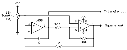
A simple triangle and square wave generator utilizing a common 1458 dual op-amp, capable of operating from very low frequencies up to approximately 10 kHz. The time interval for one half-cycle is determined by the product of resistance (R)...
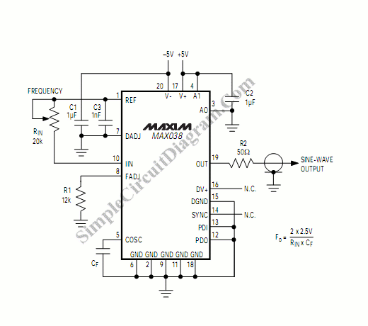
A function generator that operates within a frequency range of 0.1 Hz to 20 MHz can be easily constructed using the MAX038 integrated circuit chip. This describes a straightforward implementation of the device. The MAX038 is a precision waveform generator...
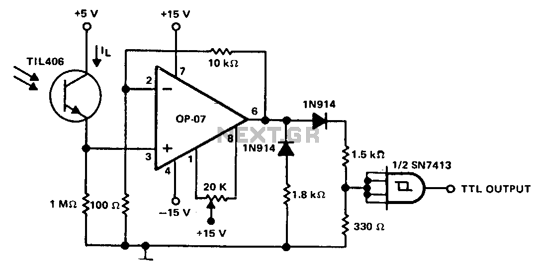
This circuit is designed to detect low light levels at the sensor, amplify the signal, and provide a TTL-level output. When the optical sensor detects low-level light, its output is small and must be amplified. An amplifier with very...
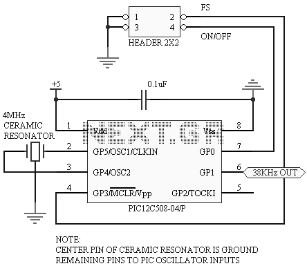
The small 8-pin PIC12C508 is pre-programmed to generate our 38KHz carrier frequency by simply pulsing I/O-pin GP1. The PIC will generate either 38KHz or 40KHz, depending on the state of GP3 when power is first applied. If you connect...

An electronic project to build a multivibrator as a basic first test instrument, ideal for troubleshooting radio repairs. Includes a how-to-use guide. An excellent beginner project. The multivibrator circuit serves as a fundamental building block in electronics, providing a versatile...
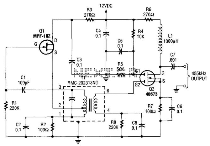
An MPF102 FET oscillator drives a dual-gate MOSFET buffer. The MPF102 is configured as a Hartley oscillator. If desired, an audio voltage can be coupled to the junction of R4, R5, and C5 with an extra coupling capacitor (~1...