
Optical Receiver Circuits

The optical receiver is a critical component in communication systems that rely on light as a medium for data transmission. The design and implementation of the optical receiver involve careful consideration of its various sections, each of which plays a specific role in ensuring effective signal processing.
The light collector, typically a lens, focuses incoming light onto the light detector. The choice of lens affects the acceptance angle and the intensity of the light reaching the photodiode. The light detector, often a silicon PIN photodiode, is selected for its sensitivity and response characteristics. Its reverse-biased operation is essential for optimal performance, allowing it to convert incident light into an electrical current. The current-to-voltage converter then transforms this current into a usable voltage signal, which is subsequently amplified by the signal amplifier to ensure that the signal can be processed without distortion.
The pulse discriminator is responsible for interpreting the amplified signal and recovering the original information. For voice signals, additional components such as frequency-to-voltage converters and audio amplifiers may be necessary to accurately reproduce the audio content. In contrast, digital data receivers require decoding circuits to manage the conversion of serial data into a format suitable for processing.
Environmental factors, such as ambient light interference, must also be considered in the design of optical receivers. The use of optical filters can mitigate the impact of unwanted light sources, though careful selection is necessary to balance light transmission and noise reduction. The overall effectiveness of the optical receiver depends on the integration of these components and their ability to work cohesively to extract and restore information from modulated light signals.The overall task of the optical receiver is to extract the information that has been placed on the modulated light carrier by the distant transmitter and restores the information to its original form. The typical through-the-air communications receiver can be broken down into five separate sections. These are: light collector (lens), light detecto r (PIN), current to voltage converter, signal amplifier and pulse discriminator. There may also be additional circuits depending on the kind of the signal being received. As an example, a receiver that is extracting voice information will need a frequency to voltage converter and an audio amplifier to reproduce the original voice signal. Computer data receivers will also need some decoding circuits that would configure the transmitted serial data bits into 8 bit words.
However, this section will concentrate on the circuits needed for processing voice information. Volume II of this book will contain additional circuits for digital data receivers. As discussed in the section on light detectors, the silicon PIN photodiode is the recommended detector for most all through-the-air communications. Such a detector works best when reversed biased. In the reversed biased mode it becomes a diode that leaks current in response to the light striking it.
The current is directly proportional to the incident light power level (light intensity). When detecting light at its peak spectrum response wavelength of 900 nanometers, the silicon PIN photodiode will leak about 0. 5 micro amps of current for each microwatt of light striking it. This relationship is independent to the size of the detector. The PIN photodiode size should be chosen based on the required frequency response and the desired acceptance angle with the lens being used.
Large PIN photodiodes will have slower response times than smaller devices. For example, 1 cm X 1 cm diodes should not be used for modulation frequencies beyond 200KHz, while 2. 5 mm X 2. 5 mm diodes will work beyond 50MHz. If a long range is desired, the largest photodiode possible that will handle the modulation frequency should be used.
Some systems can benefit from the placement of an optical filter between the lens and the photodiode. The filter can reduce the effects of sunlight and some stray light from distant street lamps. Filters can be especially effective if the light detector is going to be processing light from a diode laser.
Since laser light has a very narrow bandwidth, an optical band pass filter that perfectly matches the laser light can make a light receiver nearly blind to stray sunlight. If light emitting diode light sources are used, optical filters with a much broader bandwidth are needed.
Such a filter may be needed for some situations where man-made light is severe. Many electronically controlled fluorescent and metal vapor lamps can produce unwanted modulated light that could interfere with the light from the distant transmitter. But, in all but a few rare exceptions, band pass filters produce few overall improvements if the correct detector circuit is used.
Since no optical filter is perfectly transparent, the noise reduction benefits of the filter usually do not out weigh the loss of light through the filter. Also, if the detector is going to process mostly visible light, no optical filter should be used. This simple "high impedance" technique uses a resistor to develop a voltage proportional to the light detector current.
However, the circuit suffers from several weaknesses. If the resistance of the high impedance circuit is too high, the leakage current, caused by ambient light, could saturate the PIN diode, preventing the modulated signal from ever being detected. Saturation occurs when the voltage drop across the resistor, from the photo diode leakage current, approaches the voltage used to bias the PIN device.
To prevent saturation, the PIN must maintain a bias voltage of at le 🔗 External reference
Related Circuits
A collection of touch switch circuits is presented. A touch switch is an electronic device that allows control of a circuit simply by touching a sensor. The circuit diagram illustrates a simple design that utilizes only eight components. The...
There is a vast array of TX and RX modules available for microcontrollers. The least expensive option identified was priced at $9.99, which is reasonable, although there are memories of encountering FM receiver modules in the past. The TX (transmitter)...
The tuned circuit consists of a variable capacitor and fixed air spaced coil. For the coil, wound between 10 and 20 turns of wire on an empty tube of around 1.5 inches diameter. The turns were spaced so that...
The SC1437 is a battery overvoltage detection circuit that includes a driver for an external MOSFET. The trip point can be adjusted using an external resistor divider connected to the SENSE pin. If no external divider is used, the...
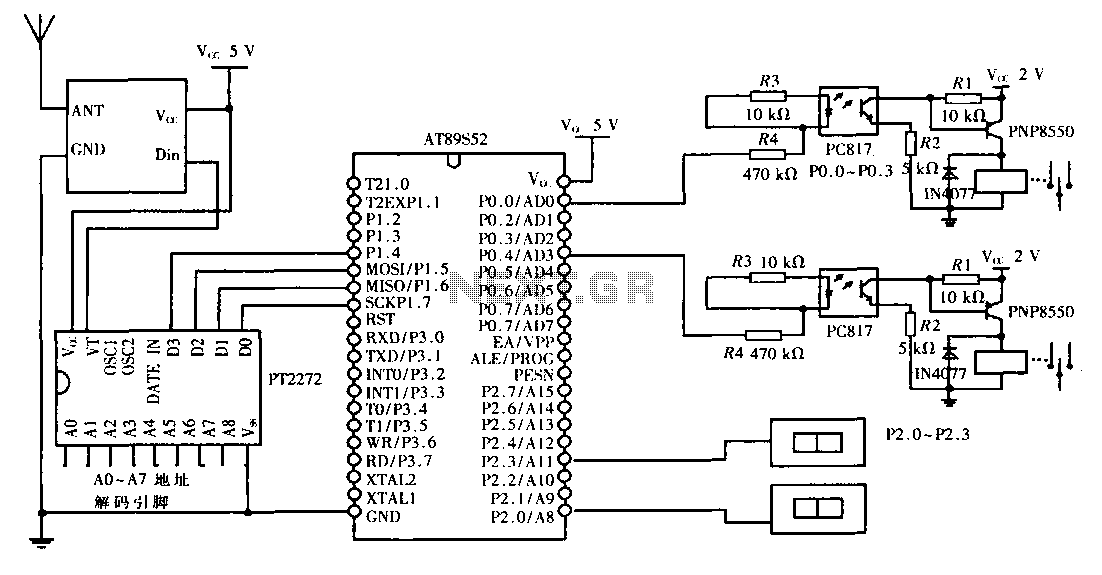
This design aims to create a long-distance wireless remote control switch lighting control system, which consists of a transmission system and a reception system. The system utilizes wireless transceiver modules for RF transmission and reception. The transmitting portion mainly...
By combining a current-reuse amplifier and a switch-based mixer, a dual-band receiver front end offers excellent performance with extremely low power consumption. The dual-band receiver front end integrates a current-reuse amplifier and a switch-based mixer to achieve high performance while...