
SC1088 AUTO SEARCH TUNING FM RADIO RECEIVER

The SC1437 circuit operates as a robust solution for battery overvoltage protection, ensuring the longevity and safety of battery systems. The adjustable trip point allows flexibility in application, accommodating various battery chemistries and configurations. The use of an external resistor divider for trip point adjustment provides a straightforward method for tailoring the circuit to specific requirements.
The internal delay feature is particularly beneficial for mitigating transient voltage spikes that could lead to false triggering of the overvoltage protection. By allowing users to select between different delay times or bypassing the delay altogether, the SC1437 adapts to different operational environments and user needs.
In the event of an overvoltage condition, the SC1437’s design ensures that the external N-channel MOSFET is driven off, effectively isolating the battery from the load and preventing potential damage. The additional functionality of the voltage comparator adds a layer of protection by immediately disconnecting the battery if the voltage exceeds a critical threshold, thereby enhancing the reliability of the overall system.
The three functional options for the overvoltage pin (active low, active high, and open-drain) provide versatility in interfacing with various control systems, making the SC1437 suitable for a wide range of applications, from consumer electronics to industrial battery management systems. The compact SOT-23 package further simplifies integration into space-constrained designs, making it an ideal choice for modern electronic applications.The SC1437 is a battery over voltage detection circuit with driver for external MOSFET The trip point is adjustable with an external resistor divider connected to the SENSE pin. The trip point is preset to a nominal trip voltage of 4. 2V if no external divider is used. Other internal trip voltages of 4. 5V and 4. 7V are available, specified by differ ent part numbers. An internal delay, with two selectable times or bypass, is on-board to suppress accidental over voltage conditions due to glitches on the battery supply volt- age, V+. The delay is externally adjustable by pulling the SEL pin high, low, or left floating. During an actual over voltage condition, the internal driver will pull the over voltage pin (OV) down to the voltage present at the V- pin.
This insures the external N-Channel MOSFET will be completely off during an over voltage condition. Supply current during the monitoring mode of operation is ap- proximately 10A. If an over voltage condition is detected, supply currents increase when the Timer is started. A voltage Comparator will engage at voltages greater than 6. 8V, which bypasses the Timer and open circuits the battery by turning off the external MOSFET This important function protects the battery during the Timer delay in the event of a charger failure. There are three functional options available. With the B option the OV pin is active low. With the L option the OV pin is active high. With the H option the OV pin is open drain, active high. All options are available in a 5 lead SOT-23 package. By Semtech Corporation 🔗 External reference
Related Circuits

A certain part of this circuit is directly connected to the AC mains; therefore, do not touch it while in operation. It is essential to exercise extreme caution when handling the AC mains supply during the construction of this...
This circuit operates at 73 MHz and is designed for controlling halogen lights through radio frequency remote control. The primary function is to toggle the power state of a halogen lamp. When the button on the remote control is...
Many amateur receivers are equipped with an S meter that does not operate logarithmically. The proposed circuit is intended to enhance such receivers. Although integrated circuits like the CA3089 or CA3189 are not commonly used today, they play a...
This ZIP file contains information about building a small radio transmitter, which has a PCB 1.75" x 2.5" (45mm x 68 mm) and has a range of about 30 yards or so. The documentation with the circuit says the...
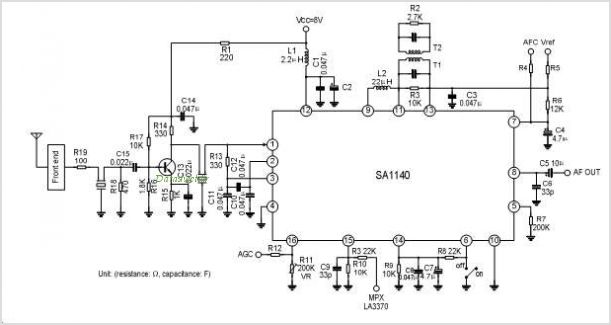
The SA1691 is a monolithic integrated circuit designed for radio cassette tape recorders, clock radios, and headphone radios. This IC includes all functions from the antenna to the audio power amplifier of AM/FM radio, produced by Silan. The SA1691 integrated...
The receiver input circuit is powered by a 60Ω generator. A low-pass filter is employed to permit the entire frequency range while maintaining uniform sensitivity. The receiver input circuit is coupled with a transmitter inductive component (Ri = 60Ω)....