
Optical switch detector with 555

The circuit described involves a phototransistor used as a light sensor, which operates in conjunction with a 555 timer IC configured in a monostable or astable mode depending on the application. The phototransistor's operation is based on the principle that it conducts current when exposed to infrared (IR) light, leading to a voltage drop across a resistor connected to its collector. This voltage drop is crucial for triggering the 555 timer.
The 1 MΩ resistor plays a pivotal role in setting the threshold voltage at which the 555 timer activates. The relationship between the collector current (Icollector) and the resistor value (R) determines how much light is needed to bring the voltage at the collector down to the threshold of VCC/3. By adjusting the resistor value, the sensitivity of the phototransistor can be modified, allowing for the detection of varying light levels. For high-sensitivity phototransistors, a lower resistance is required, while weaker phototransistors necessitate higher resistance values. The inclusion of a trimmer resistor allows for fine-tuning of the sensitivity, providing flexibility in different lighting conditions.
The 555 timer IC, known for its robustness, can drive a variety of output devices, including relays and MOSFETs, making it suitable for applications such as alarms or switching mechanisms. In scenarios where an action is required upon the interruption of light (e.g., a burglar alarm), the output of the 555 timer may need to be inverted. This inversion can be achieved using a small bipolar transistor arranged in an inverting configuration. Alternatively, the configuration can be modified by repositioning the phototransistor and resistor, ensuring that the voltage at the collector drops below VCC/3 when the light is blocked.
Overall, the described circuit provides a versatile and effective means of detecting IR light and triggering various outputs based on the light's presence or absence, suitable for numerous electronic applications.When the phototransistor is stroken by IR light it conducts and the voltage between the 1Mohm resistor(arbitrary) and the phototrans drops from VCC to lower values. When the voltage drops lower than VCC/3 the 555 is triggered and goes high (from 0 TO VCC). The amount of light that strike the phototrans necessary to bring his collector to VCC/3 is determined by the resistor (Vdrop = Icollector * R , so , if Vdrop= 2*VCC/3, the resistance needed to set the threshold on current is R=2*VCC/(Icollector*3)).
High sensibility phototrans would need a smaller resistor, and weaker phototransistors higher value resistor, you can also use a trimmer to set the on threshold level with precision. The time of phototransistor isn't critical. The 555 has high current capability and can drive various devices, such as Bipolars, relays, bipolars+relays, mosfets, mosfets + totem pole , or give a logic output.
In case you need to trigger something when the gate is blocked (for example a burglar alarm, or a multistage coilgun) you need to invert the output, which is accomplished using a small bipolar transistor wired in an inverting setup (see pic) or swapping the positions of phototransistor with the resistor, so the voltage will drop under VCC/3 when blocked: The formula to determine the resistance to turn off at Icollector is R=VCC/(Icollector*3). 🔗 External reference
Related Circuits
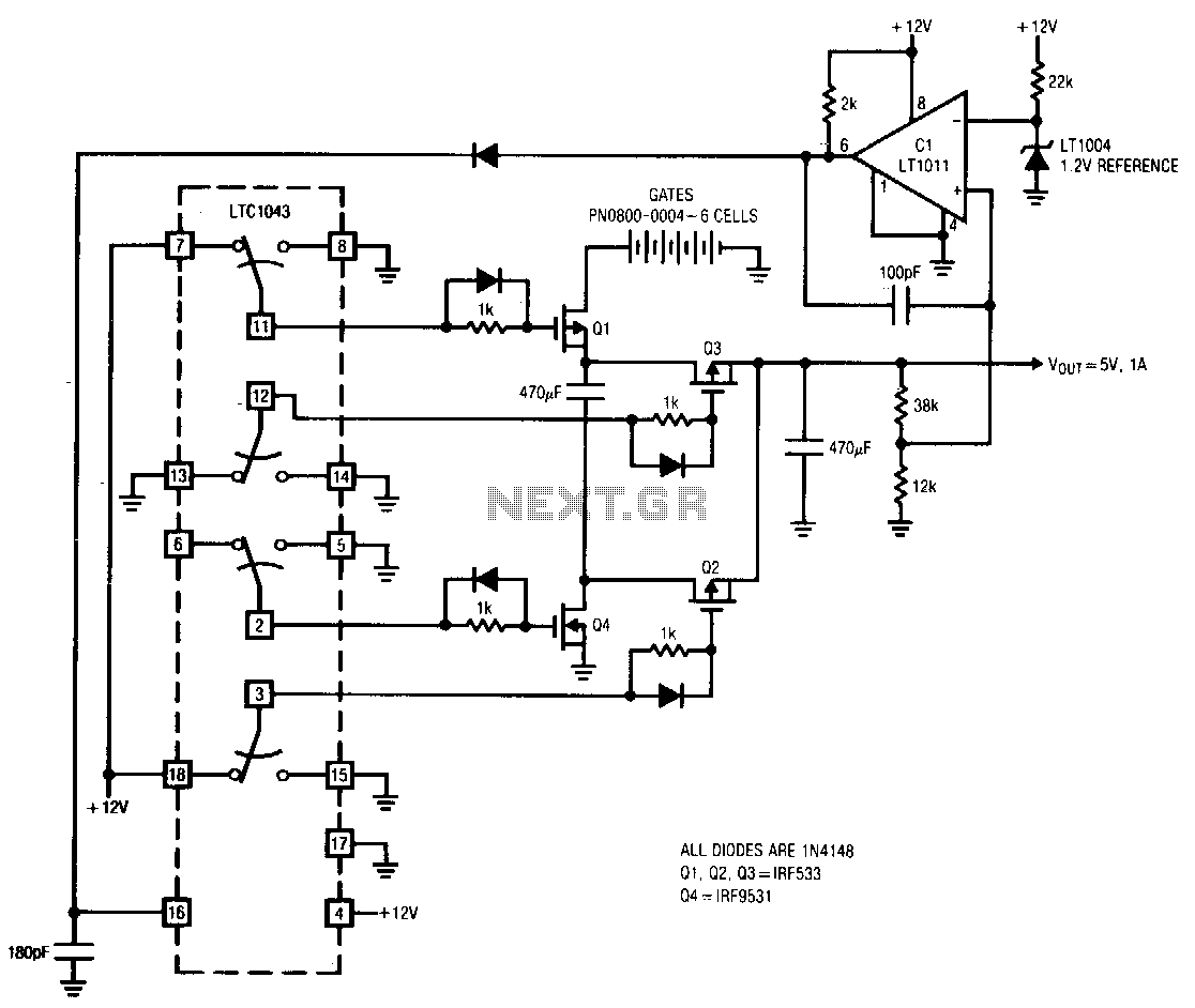
The LTC10432 switched-capacitor building block provides non-overlapping complementary drive to the Q1 to Q4 power MOSFETs. The MOSFETs are arranged such that C1 and C2 are alternately placed in series and parallel configurations. During the series phase, the +12...
Wilf Rigter simplified this circuit a bit, made it phototropic, and doubled it up to yield a photopopper design in a post later the same day. I’ve got this design written up elsewhere in the library. The circuit described is...
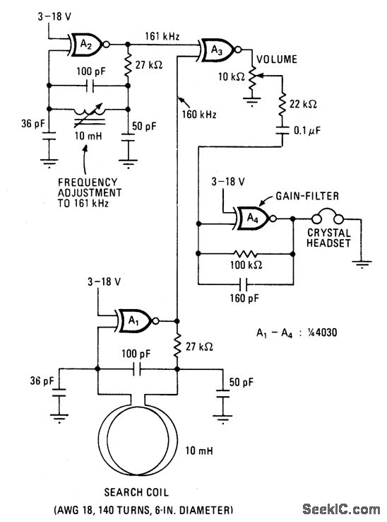
This battery-powered metal detector utilizes four exclusive-OR gates found in the 4030 CMOS integrated circuit. The gates are configured as twin oscillators, with a search coil acting as the inductance element in one of the oscillators. When the coil...
This circuit can be constructed using readily available, low-cost components, some of which may even be found in a junk box. The specified value of 22 for resistor R1 results in an average current of approximately 65 mA flowing...
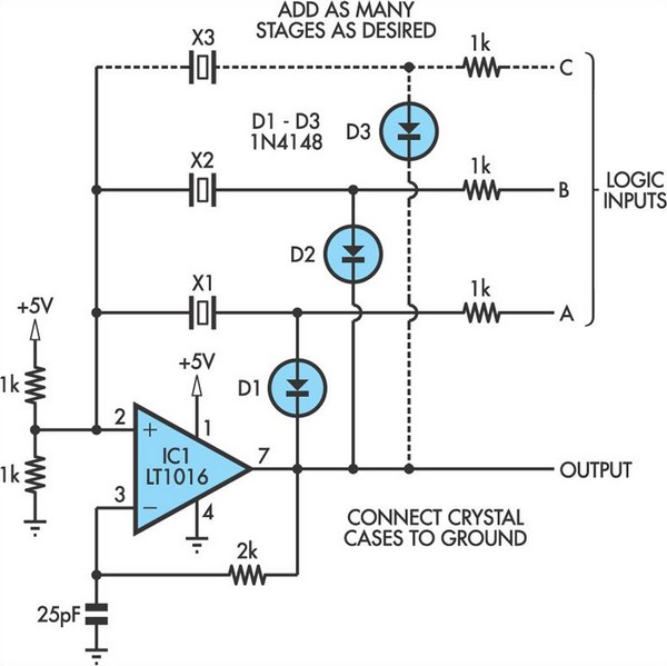
This oscillator circuit allows crystals to be electronically switched through logic commands. The circuit is best comprehended by initially disregarding all crystal components. The oscillator circuit described functions as a frequency generator that utilizes the properties of quartz crystals to...
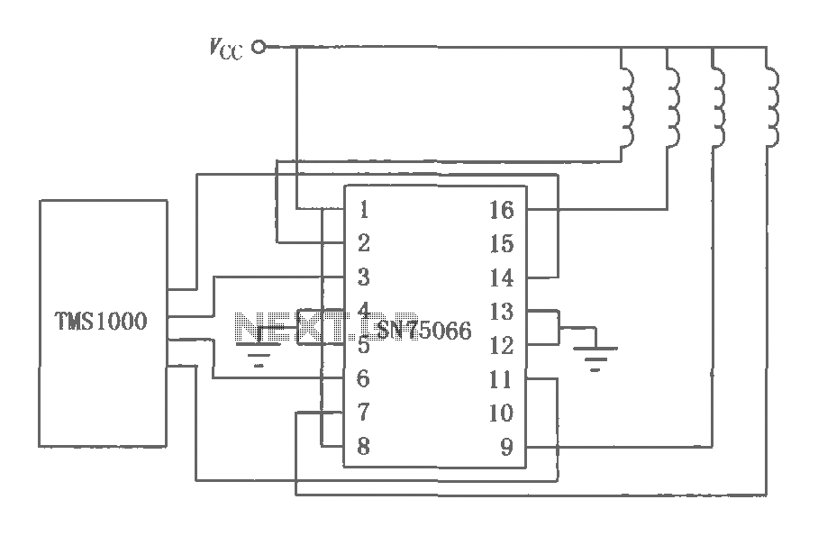
The SN75064 to SN75067 series consists of monolithic, high-voltage, high-current Darlington switch output terminations. These devices include clamp diodes, making them suitable for inductive loads. Each package contains four Darlington pairs that can be connected in parallel to achieve...