
Optical transmission detection circuit

The circuit consists of a phototransistor that converts the incoming optical signals into electrical signals. The output from the phototransistor is fed into a series of four operational amplifiers configured to amplify the signal for further processing. Each operational amplifier can be set up in different configurations, such as inverting, non-inverting, or differential, depending on the desired characteristics of the output signal.
The operational amplifiers play a crucial role in enhancing the sensitivity and accuracy of the total energy detection. By adjusting the gain of each amplifier, the circuit can be fine-tuned to respond appropriately to varying light intensities, ensuring reliable performance under different conditions. The amplified signal can then be processed to determine the total energy of the optical pulse, allowing for effective monitoring and evaluation of the optical fiber's performance.
In practical applications, this total energy detector can be used in conjunction with diagnostic equipment to assess the integrity of optical fibers in communication systems. By comparing the detected energy levels with known standards, it is possible to identify potential issues such as attenuation or signal degradation, thereby facilitating timely maintenance and ensuring optimal communication efficiency.In this circuit, phototransistor and four operational amplifier take the action of total energy detector, to detect the total energy of pulse optical transported by the optical cable communication system. If the light intensity of singal source remains the same, then this circuit can be used to test and compare the situation of optical fiber, it also can b..
🔗 External reference
Related Circuits

The circuit utilizes a 4-bit encoder to generate data, which is then modulated using an RF modulator for transmission. On the receiving end, the signal is demodulated, and a decoder retrieves the 4-bit data. The pin configuration for the...

This circuit design generates a stable 1 kHz sine wave using an inverted Wien bridge configuration with components C1-R3 and C2-R4. It offers a variable output, low distortion, and low output impedance to ensure good overload capability. The circuit...

RS232 to RS485 Converter Circuit Schematic. RS232 to RS485 converters are primarily utilized in industrial and commercial settings. The RS232 to RS485 converter circuit is designed to facilitate communication between devices using different serial communication standards. RS232 is commonly found...
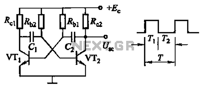
Common non-sinusoidal oscillator circuit, waveform and frequency formula - square wave oscillator - self-excited multivibrator The common non-sinusoidal oscillator circuit, specifically the square wave oscillator, is a fundamental electronic circuit utilized to generate square wave signals. It operates based on...

Circuit audio peak indicator circuit schematics. Circuit Electronics, schematics for audio peak indicator circuit. An audio peak indicator circuit is designed to visually represent the peak levels of an audio signal, providing critical information for audio engineers and musicians regarding...
This is a design circuit for a soft light dimmer. The circuit utilizes the IGBT STGP10N50A and the TS555 timer as the main components. The timer is triggered by the zero crossing voltage pulse. The time constant, determined by...