
Audio peak indicator circuit

An audio peak indicator circuit is designed to visually represent the peak levels of an audio signal, providing critical information for audio engineers and musicians regarding signal strength and potential clipping. The circuit typically consists of a few essential components: a diode, a capacitor, a resistor, and an LED or a series of LEDs for visual indication.
The input audio signal is fed into the circuit, where it first encounters a diode. The diode's role is to rectify the audio signal, allowing only the positive half-cycles to pass through. This rectified signal is then smoothed out by a capacitor, which charges to the peak voltage of the incoming audio signal and discharges slowly, providing a stable voltage level that corresponds to the peak amplitude.
A resistor is often included in parallel with the capacitor to control the discharge rate, allowing the LED to remain lit for a short duration after the peak has passed. This creates a more noticeable indication of the peak level. The LED is connected in such a way that it lights up when the voltage across the capacitor reaches a certain threshold, indicating that the audio signal has hit a peak level.
The circuit can be calibrated to respond to specific voltage levels, making it adaptable for various audio applications. By adjusting the resistor and capacitor values, the response time and sensitivity of the peak indicator can be fine-tuned to suit different audio environments. This circuit is particularly useful in live sound reinforcement, studio recording, and broadcasting, where monitoring audio levels is crucial to maintaining sound quality and preventing distortion.Circuit audio peak indicator circuit schematics Circuit Electronics, Schematics for audio peak indicator circuit Circuit Electronics.. 🔗 External reference
Related Circuits
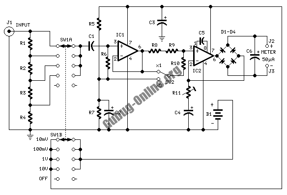
This design circuit is used to activate circuitry and an analog meter for sensitive DC current measurements. A subsequent inquiry raised the possibility of measuring AC microamperes, which inspired the idea for this circuit. The circuit is designed to facilitate...
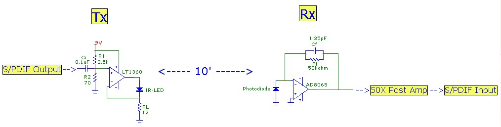
This article aims to illustrate a basic optical LED wireless link for transmitting high-definition (HD) S/PDIF digital audio streams. Circuit designs for both the transmitter (optical modulator) and receiver are provided, utilizing cost-effective op-amp configurations. Specific components are listed,...
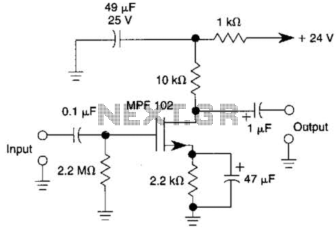
This JFET preamplifier has a gain of approximately 20 dB and a bandwidth exceeding 100 kHz. It is useful as a low-level audio amplifier for high-impedance sources. The described JFET (Junction Field Effect Transistor) preamplifier is designed to amplify low-level...
The lamps are usually used as ballast or electronic ballast inverter. Here it is used to reduce voltage capacitor reactance. Interesting is also the method of ignition of the auxiliary electrodes involved over 150 Ohm resistors. To start simply...
This circuit generates dual-tone bell sounds similar to those found in standard doorbell units. It is applicable in various contexts beyond doorbells. The circuit, as depicted in the diagram, produces a "Ding-tone" when switch P1 is pressed and a...
If the amp is built on bipolar transistors, and the preamp/crossover on FETs, then they were designed by different guys, right? Not this amp. Here, a strong, experienced designer's hand is evident from schematic to parts layout, PCB routing...