
Optimized 6-element UHF Yagi Antenna

The described antenna system consists of multiple elements, including a dipole and additional radiating elements, which are integral to its design and functionality. The diameter of these elements is critical for ensuring optimal performance. The specified range for the elements is between 5 mm and 8 mm, while the dipole's diameter is recommended to be 12 mm, within a range of 8 mm to 12 mm. This flexibility in diameter allows for variations in manufacturing and assembly without necessitating adjustments to the overall length or spacing of the antenna elements, which is advantageous for maintaining consistent performance characteristics.
The boom serves as the structural support for the antenna elements. It is essential that the boom is constructed from an isolator material such as plastic, wood, or fiberglass, especially when the antenna is mounted vertically. This is to prevent any distortion of the radiation pattern, which could adversely affect the antenna's performance. The thickness of the boom is specified to vary between 10 mm and 15 mm, providing a robust structure that can support the antenna elements securely while also minimizing interference with the antenna's radiation characteristics.
All elements, with the exception of the dipole, are electrically connected to the boom. This connection can be achieved through various mounting techniques, either by mounting the elements on top of the boom or through it. The choice of mounting method may depend on the specific design requirements and the intended application of the antenna. Proper installation and alignment of the elements are crucial to ensure that the antenna operates effectively within its intended frequency range.
Overall, this antenna design emphasizes flexibility in construction and material choice while ensuring that performance is not compromised through careful attention to the dimensions and mounting techniques of its components.The elements diameter of the antenna may vary between 5...8mm and the dipole diameter may vary between 8...12mm (12mm recommended) without the need of changing anything to the length or spacing. All elements except the dipole are electrically connected to the boom and may be mounted on top or through it.
The thickness/diameter of the boom may vary between 10...15mm. Use an isolator type boom (plastic tube, wood, fiberglass) if you mount the antenna vertical to prevent distorion of the radiation pattern. 🔗 External reference
Related Circuits
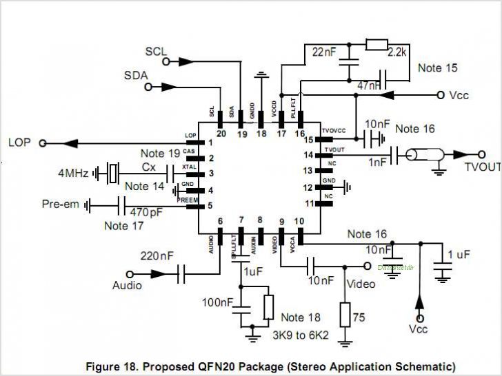
MC44BS374CA: PLL Tuned UHF and VHF Audio Video High Integration Modulator MC44BS374CA The MC44BS374CA Audio and Video Modulator is for use in VCRs, set-top boxes, and similar devices. By Freescale Semiconductor, Inc The MC44BS374CA is a highly integrated audio and...
This small circuit is a linear amplifier for driving small UHF TV transmitters. Its gain is 7 dB and can amplify a signal between 450-800 MHz. You can drive the circuit with 1 to 1.5 Watts signal. Better use...
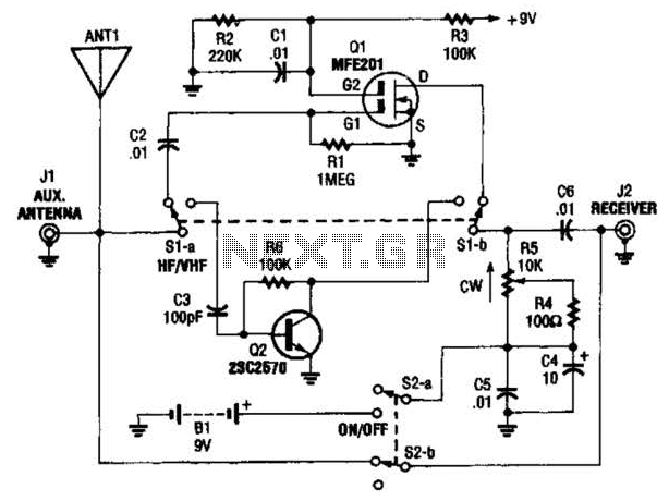
The AA-7 active antenna consists of two active components: Q1 (an MFE201 N-channel dual-gate FET) and Q2 (a 2SC2570 VHF silicon transistor), which form the foundation for two independent, switchable RF preamplifiers. The AA-7 active antenna is designed to enhance...
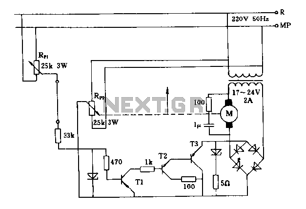
The FIG potentiometer RP2 has a sliding contact that is directly connected to the antenna. The system operates such that only when potentiometers RP1 and RP2 are positioned identically, do the non-conductive transistors and rectifier bridge remain off, resulting...
A typical low-cost FSK modulator, TA0038, is implemented by injecting the modulation voltage into the phase-locked loop (PLL) of the carrier synthesizer. This can be achieved in two ways: by summing the modulation voltage with the loop error voltage...
The circuit diagram of a TV antenna is sourced from the technical information provided by Chinaicmart. For more detailed information or additional circuit designs, further inquiry may be necessary. The circuit diagram for a TV antenna typically consists of several...