
5 Watt UHF TV Linear amplifier

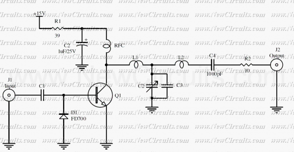
The circuit functions as a linear amplifier specifically designed for UHF TV transmission applications, operating effectively within the frequency range of 450 to 800 MHz. The amplifier achieves a gain of 7 dB, making it suitable for boosting weak signals typical in UHF broadcasting. The input signal level can be in the range of 1 to 1.5 Watts, which allows for compatibility with various UHF transmitters.
To ensure optimal performance, a double-layer printed circuit board (PCB) is recommended. The second layer of the PCB should be connected to ground to provide improved shielding and signal integrity, reducing potential interference and noise that could affect the amplifier's performance.
The circuit requires a stabilized power supply, rated at 25 volts and capable of supplying at least 5 Amps. This ensures that the amplifier operates reliably under various load conditions without voltage fluctuations that could compromise its performance.
The active component used in this design is a transistor housed in a SOT-122A package. It is critical to handle this component with care, as it is noted to be toxic. Proper safety measures should be taken when working with the circuit to mitigate any health risks associated with the transistor.
Tuning the amplifier can be accomplished by adjusting the two variable capacitors incorporated into the design. This allows for fine-tuning of the circuit to achieve the desired frequency response and optimize signal amplification.
Additionally, it is essential to use heat sinks for both transistors, particularly for the BLW89 transistor. This is necessary to dissipate heat generated during operation, preventing thermal overload and ensuring the longevity and reliability of the amplifier circuit. Proper thermal management is crucial in maintaining the performance and stability of the amplifier under continuous operation.This small circuit is a Linear amplifier for driving small UHF TV transmitters. Its gain is 7dB and can amplify a signal between 450-800 MHz. You can drive the circuit with 1 to 1,5 Watts signal. Better use double layer PCB with the second layer connected to earth. Use a stabilized power supply 25 volts and at least 5Amps. The transistor case is the SOT-122A and be careful because the transistor is very toxic for your health. Tuning can be achieved turning the two variable capacitors. Do not forget to use heat sink for both transistors, specially for the BLW89 and it would
Related Circuits

A simple linear voltage-controlled amplifier can be constructed with one operational amplifier (op amp) and two junction field-effect transistors (JFETs). This amplifier can achieve an 80-dB dynamic control range with less than ±0.2% linearity error for 0 V. The described...
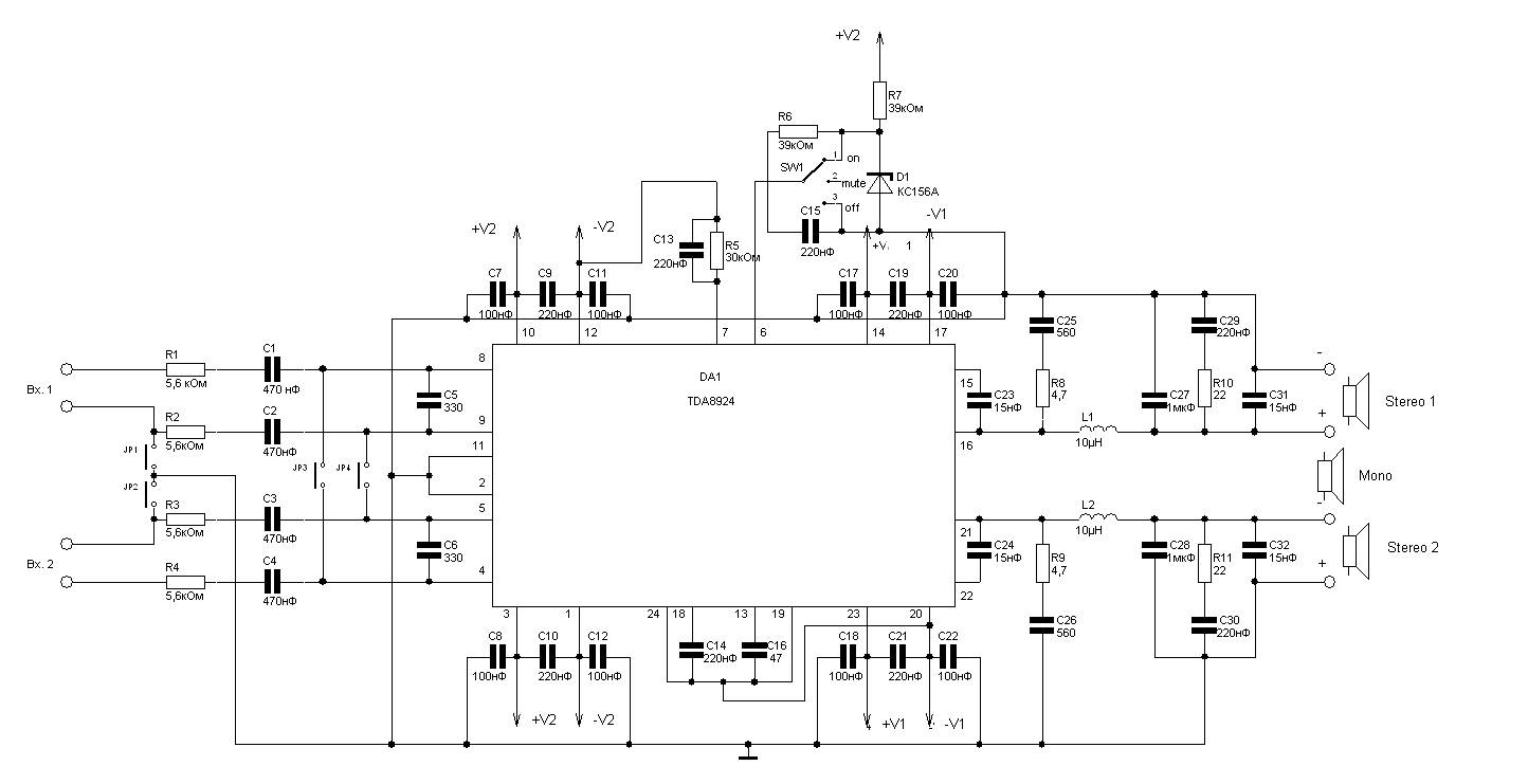
240W power amplifier circuit based on the TDA8924 class D design. This integrated circuit features short-circuit protection at the output, thermal protection, and safeguards against acoustic damage from inrush currents during power on and off. The schematic allows for...
The original version of P05 has been around for a very long time now (around 4 years), and there are some worthwhile reasons for the updates. Although the performance of the original was not lacking in any way, I...
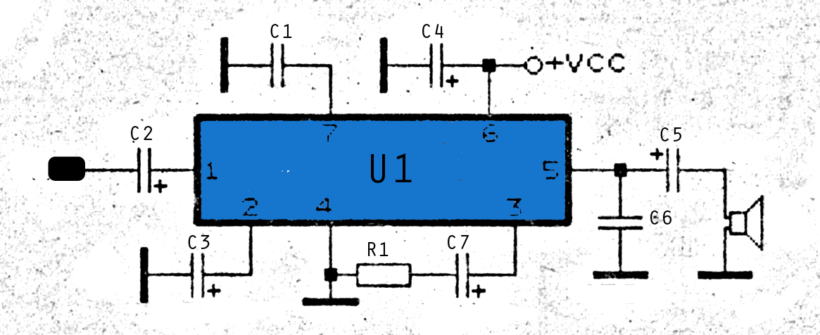
The amplifier circuit is highly suitable for use in FM radio receivers. It requires a supply voltage of 8 to 25 Volt DC and can deliver a maximum output power of 0.15W. Refer to the schematic below. The described amplifier...
A professional suggestion for those interested in improving sound. The circuit constitutes the part of input mixing console sound from the microphone or source of high level. It can be used on its own or be multiplied to the...
The RF circuit is a C-Class power amplifier. It is used in the last stage of transmitters. Its maximum power output is about 1 Watt. The circuit can be used in 3 frequency ranges: 30-100-200 MHz. More: The P-Out...