
Flip-flop flasher

The described circuit utilizes an astable multivibrator, which is a type of oscillator that continuously switches between its high and low states without requiring any external triggering. In this configuration, the flashing rate is determined by the time constants of the resistors and capacitors used in the circuit.
For a positive earth system, NPN transistors are employed, which are typically used for their ability to switch on and off quickly, allowing for efficient control of the lamp's flashing. The NPN transistors are connected in such a way that they alternately turn on and off, creating the desired flashing effect. The timing components, usually consisting of resistors and capacitors, set the frequency of the oscillation, effectively controlling the number of flashes per minute.
Conversely, when utilizing PNP transistors, the circuit configuration is modified to accommodate the different characteristics of these transistors. PNP transistors conduct when their base is pulled low relative to their emitter, which is connected to a positive voltage in a positive earth system. The design must ensure that the timing components are appropriately selected to achieve the same flashing rate of approximately 60 flashes per minute.
Overall, the astable multivibrator circuit is a versatile solution for generating flashing lights in various applications, with the choice of transistor type allowing for compatibility with different electrical systems.The flashing action is provided by a simple astable multivibrator timed to give a flashing rate of about 60 flashes for each lamp per minute. Circuit for positive earth systems uses NPN transistors The other uses PNP transistors.
Related Circuits

A magnet is positioned on the door, while a magnetic reed switch is installed on the door casing. When the door is closed, the circuit is disabled. When the door is opened, the circuit becomes active. In this circuit design,...

As an alternative to a bipolar transistor, a lamp flasher can be constructed using two power FETs. Similar to other flasher circuits, this circuit alternately switches the... The proposed lamp flasher circuit utilizes two power Field-Effect Transistors (FETs) to control...

This application involves a static switch circuit where the control logic is implemented using a flip-flop, which is driven by a unijunction transistor. The flashing rate of the circuit can be adjusted, ranging from approximately 0.1 seconds to a...
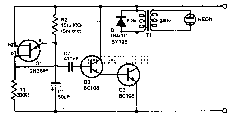
The voltage required to ignite the neon tube is generated by utilizing a standard filament transformer (240-6 V) in reverse. The battery drain is minimal, approximately 1 to 2 milliamps for a nine-volt battery. The pulses from Q1, a...
A simple circuit for sequentially flashing Christmas light strings or other similar low-power lamps. The socket symbols may represent single bulbs or sockets for lamp strings. The load must operate from DC since the SCRs rectify the line voltage....

A 555 timer is used to drive a CMOS counter in this device, which employs an RCA CA3079 zero-voltage switch to control triacs TR1 through TR4. This circuit can be utilized for sequencing lamp displays, among other applications. Caution...