
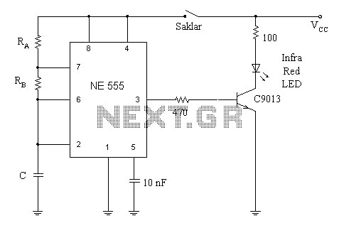
555 timer as a flip-flop

The circuit in question likely employs a timing mechanism to achieve the specified output signal behavior. A common approach to generate such timing sequences is through the use of a 555 timer IC configured in monostable mode.
In this configuration, when a trigger signal is applied to the timer, it produces a high output for a predetermined duration, which in this case is set to 0.5 seconds. The duration of the high output is determined by the values of the resistor (R) and capacitor (C) connected to the timer. The time period (T) can be calculated using the formula T = 1.1 * R * C, where R is in ohms and C is in farads.
After the high output period, the signal goes low for 1.33 seconds. To achieve this, a second timing circuit or a delay mechanism can be integrated. This could be accomplished with another 555 timer in a similar configuration or by using a microcontroller that can easily handle multiple timing sequences.
If a microcontroller is utilized, it can be programmed to set the output pin high for 0.5 seconds and then low for 1.33 seconds using simple timing functions. The microcontroller's versatility allows for easy modifications to the timing parameters without the need for physical component changes.
Additional considerations include ensuring that the power supply voltage levels are appropriate for the components used, as well as implementing debouncing mechanisms if the trigger signal is sourced from a mechanical switch. Proper decoupling capacitors should also be placed near the power supply pins of the ICs to minimize noise and ensure stable operation.
Overall, the circuit design must be carefully analyzed to identify the root cause of the issue affecting the output signal, whether it be incorrect component values, wiring errors, or potential hardware faults.I have it set up so that I get an out put signal that goes High for about 1/2 second, and then goes low for about 1.33 seconds. The problem is that.. 🔗 External reference
Related Circuits

This coil gun design utilizes arbitrary on/off times that are calculated based on the basic equations of motion, rather than chosen randomly. The coils do not activate at uniform intervals; the first coil remains energized for the longest duration...
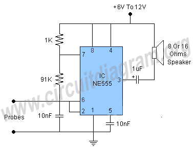
This water level alarm circuit can be utilized as a water level indicator to monitor the desired water level in various applications, such as tanks, swimming pools, or any location where water is stored. The circuit is constructed using...
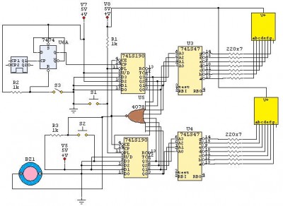
This is a 24-second countdown timer circuit designed for automatic control of electronic loads. The timer circuit utilizes fast 74LS Schottky integrated circuits (ICs). A 24-second countdown begins when switch S3 is off and switch S2 is pressed. Switch...
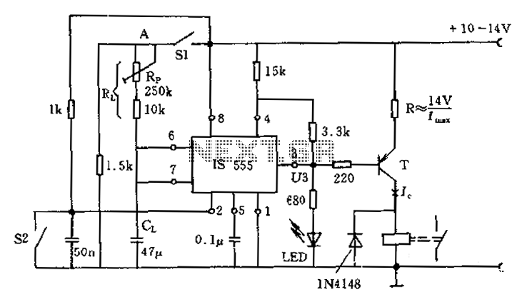
The circuit for the photoelectric switch S1 functions as a control switch for the luggage room light. In its closed operating state, the voltage is positive. If S2 is closed, irrespective of the state of S1, the output terminal...
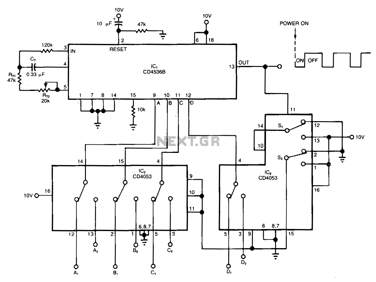
The timer circuit provides independent control over the output's on and off intervals, which can vary from 0.055 seconds to 30 minutes, and remains relatively unaffected by power-line transients. IC1 is a CMOS programmable timer chip that consists of...
A simple circuit diagram illustrates a schematic for a remote control system, which consists of two components: a transmitter and a receiver. The transmitter circuit is controlled by the NE555 integrated circuit (IC). This system operates by detecting the...