
Opto-Isolated-Input 4-Digit Voltmeter

A Voltage-to-Frequency (V/F) converter is a critical component in various electronic applications, enabling the conversion of an analog voltage signal into a corresponding frequency signal. This conversion process is essential for interfacing analog signals with digital systems, such as microcontrollers or digital signal processors.
In this context, the frequency counter serves as a measurement tool that quantifies the frequency output from the V/F converter. The relationship established between the input voltage and the output frequency is linear, meaning that as the input voltage increases, the output frequency also increases proportionally. This characteristic allows for precise measurements and monitoring of voltage levels in real-time applications.
Typically, the V/F converter operates by utilizing an internal oscillator whose frequency is modulated based on the input voltage. The output frequency can be expressed mathematically as:
\[ f_{out} = k \cdot V_{in} \]
where \( f_{out} \) is the output frequency, \( V_{in} \) is the input voltage, and \( k \) is a constant that defines the sensitivity of the converter.
For effective operation, the system should ensure that the input voltage remains within a specified range to prevent saturation or distortion of the output frequency. The use of a frequency counter for a measurement duration of 1 second provides a stable and accurate reading, allowing for reliable monitoring of voltage levels.
In practical applications, such V/F converters are utilized in data acquisition systems, telemetry, and control systems where analog signals need to be processed or transmitted in a digital format. The integration of a frequency counter enhances the usability of the V/F converter by providing a straightforward means of visualizing and quantifying the voltage levels in real-time.The voltage that control a V/F converters will be displayed if we use a frequency counter, which is directly proportional to the input voltage. A 1 second time. 🔗 External reference
Related Circuits
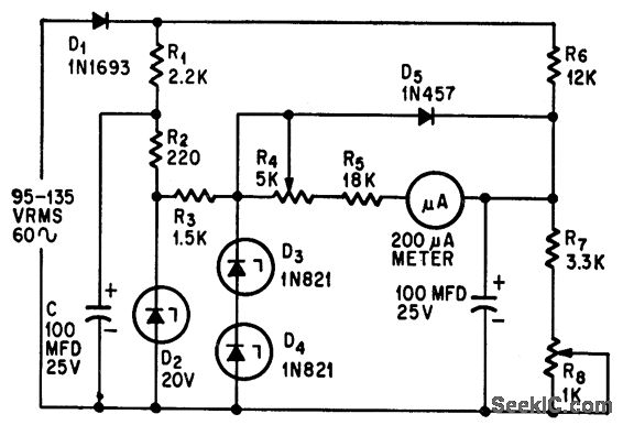
This circuit measures alternating current (AC) voltages in the range of 95 to 135 volts with an accuracy of 0.6%, utilizing a standard meter that has a 2% accuracy rating. The circuit employs Zener diodes to provide a stable...
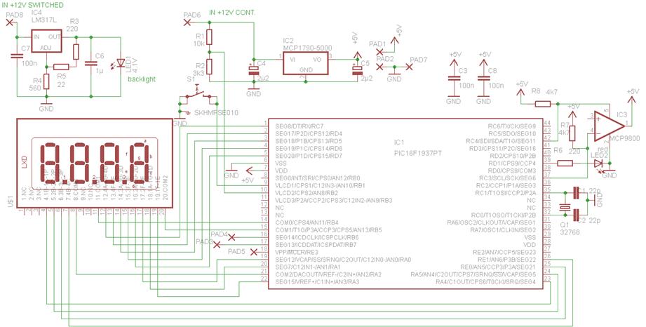
This device is designed to replace the original digital clock in a Fiat Ducato manufactured between 1992 and 1994. It is mounted above the inside rearview mirror. The original clock has limitations, including poor accuracy, a singular time display,...
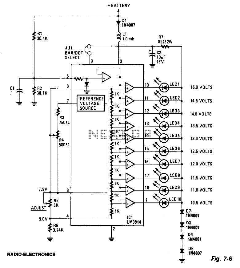
This screen utilizes ten LEDs to indicate a voltage range from 10.5 to 15 volts, with each LED corresponding to a 0.5-volt increment. The core component of the circuit is the LM3914 LED bar graph/display driver. A trimming potentiometer,...

An AC millivoltmeter - calibrated in dB - with a range of 30V down to 3mV full scale (80dB range) would be extremely useful. Attach a microphone (electret mic capsules are quite good), and you have a relative sound...
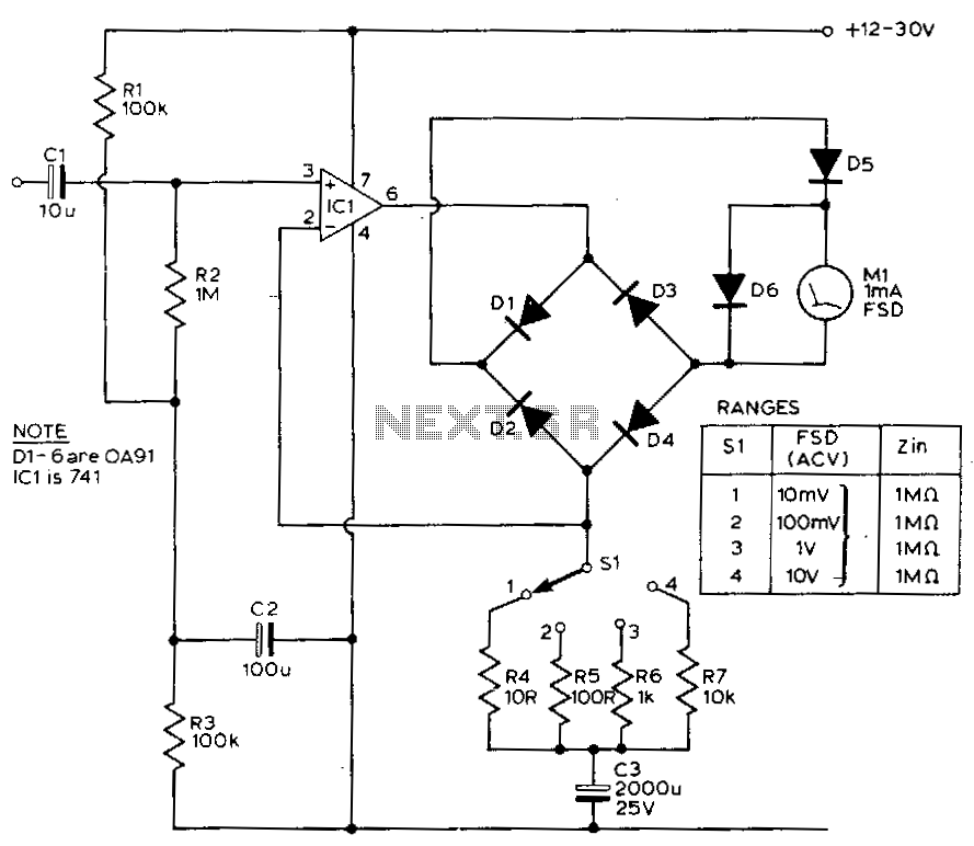
This circuit exhibits a flat frequency response from 8 Hz to 50 kHz, maintaining a -3 dB level at the 10 mV range. Furthermore, while the upper frequency limit remains consistent across less sensitive ranges, the lower frequency limit...
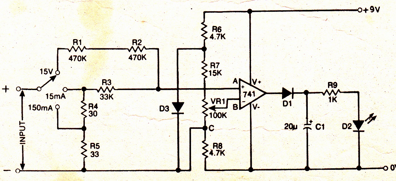
A simple electronic multimeter offers an affordable alternative for hobbyists deterred by the high cost of conventional multimeters. This device is designed to measure three ranges: (i) 0-15V, (ii) 0-15mA, and (iii) 0-150mA, with the possibility of extending the...