
Oscillator

The MOC5010 is a linear opto-coupler that enables electrical isolation between different circuit sections while allowing for signal transmission. This component is particularly useful in applications where it is critical to prevent high voltages or noise from affecting sensitive electronic systems.
The circuit typically consists of an LED and a phototransistor housed within a single package. The LED, when activated by an input signal, emits light that is detected by the phototransistor. The linear characteristics of the MOC5010 allow for a proportional relationship between the input and output signals, making it suitable for analog signal isolation.
In practical applications, the MOC5010 can be used to isolate audio signals, ensuring that ground loops and other interference do not compromise audio quality. In medical electronics, it provides a safe means to interface patient monitoring devices with high-voltage equipment, safeguarding against electrical shocks.
The circuit design should include appropriate resistors to limit the current through the LED and to set the gain of the phototransistor. Additionally, bypass capacitors may be included to filter out noise and stabilize the power supply. Proper layout considerations, such as minimizing trace lengths and separating high-voltage and low-voltage sections, are essential to enhance performance and reliability.
Overall, the MOC5010-based linear opto-coupler circuit is a versatile solution for achieving electrical isolation in a wide range of electronic applications, ensuring both safety and signal integrity.Here s a design circuit for linear opto coupler circuit that is based on MOC5010 and can be used to isolate a circuit from main grid, audio interface, in medical electronics and many other applications. Here s th .. 🔗 External reference
Related Circuits
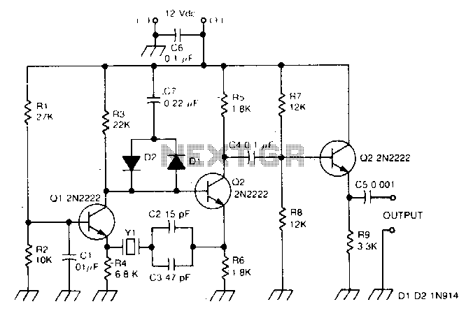
This circuit operates effectively within the frequency range of 50 kHz to 500 kHz. Minor component modifications are required for functioning at higher frequencies. For frequencies exceeding 3000 kHz, it is advisable to choose a transistor that offers moderate...
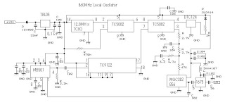
This 860 MHz Phase Locked Loop (PLL) oscillator circuit is designed for a 1200 MHz transverter's local oscillator with 435 MHz rigs. The oscillator utilizes Toshiba PLL synthesizer integrated circuits (ICs). The TC9122P serves as a preset counter for...
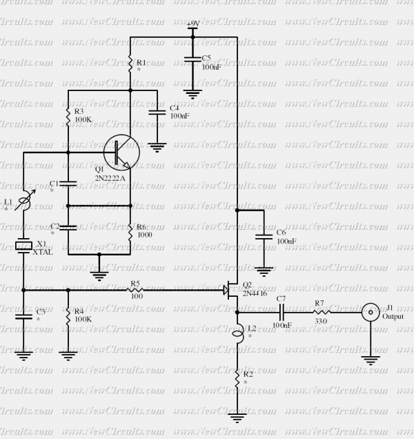
This crystal oscillator is designed to operate with fundamental crystals with less than 1 mW dissipated in the crystal. The signal current is filtered by the crystal and develops a voltage across a capacitor with about 500 ohm of...
More: A comprehensive electronic schematic is essential for understanding the functionality and design of electronic circuits. It typically includes various components such as resistors, capacitors, diodes, transistors, and integrated circuits, each represented by standardized symbols. The interconnections between these...
A tone generator operates on as little as 1.5 VDC using the Sallen-Key configuration. The tone generator will be applied to implement a phantom-powered signal source for testing balanced microphone inputs. Textbooks and web pages typically depict the Wien...
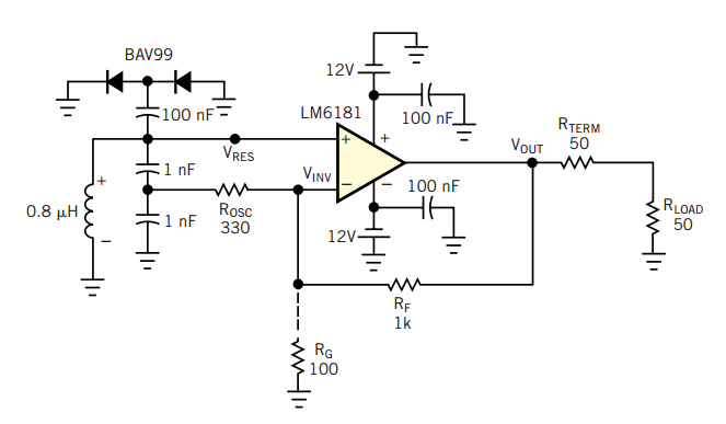
A current-feedback amplifier is a well-known component with many uses. Its basic block diagram shows that its input stage is a voltage follower in practice, a symmetrical emitter follower. The configuration samples the output current, converts it to voltage...