
Oscillator interfaces data for tv

The circuit utilizes three inverters from the 74LS04 hex inverter IC to create an oscillator configuration. The frequency of oscillation is primarily determined by the external capacitor C1 and the resistors associated with the circuit. The capacitor is essential for tuning the circuit to resonate at the desired frequency, which corresponds to a specific television channel. This fine-tuning capability is crucial for optimal signal reception and stability.
The inclusion of potentiometer R1 serves dual purposes. As a variable resistor, it allows for the adjustment of the mixing input to the circuit. This adjustment affects the contrast ratio, which is vital for enhancing the visual quality of the output signal. By manipulating R1, users can achieve the best possible viewing experience, ensuring that the picture quality is clear and well-defined.
The fourth gate within the 74LS04 acts as a buffer, providing additional stability to the oscillator circuit. Buffers are critical in preventing signal degradation and ensuring that the oscillation remains consistent and reliable. The buffering action helps to isolate the oscillator from any variations in load or supply voltage, which could otherwise affect performance.
Overall, this configuration of the 74LS04 not only facilitates the generation of a stable oscillating signal but also incorporates features that enhance user control over the output quality, making it suitable for applications in television signal processing.Three gates of a 74LS04 form the oscillator circuit. Capacitor Cl allows fine-frequency adjustment to a specific television channel and helps stabilize the circuit. Potentiometer Rl acts as the mixing input and provides adjustment of the contrast ratio for the best viewing.
A fourth gate buffers and helps stabilize the oscillator.
Related Circuits
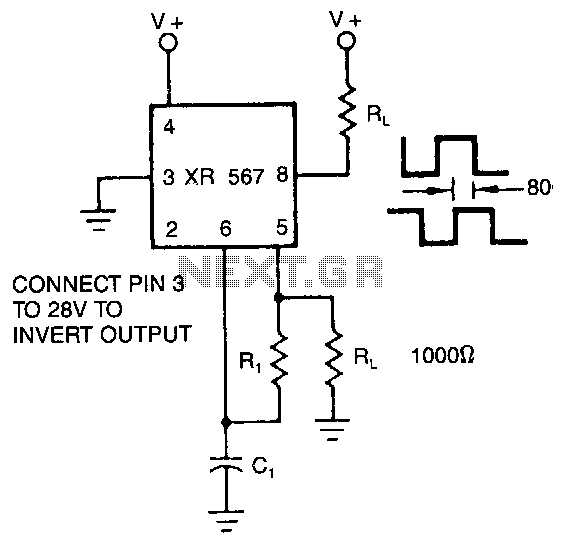
The XR-567 operates as a precision oscillator, providing two distinct square-wave outputs at pins 5 and 8, which are nearly in quadrature phase with one another. Due to the internal biasing configuration, the typical phase shift between the two...

The CA3140 is a 4.5 MHz BiMOS operational amplifier featuring MOSFET inputs and a bipolar output. This operational amplifier integrates the benefits of PMOS transistors and high voltage performance. The CA3140 operational amplifier is designed to provide high-speed performance while...
This circuit is a low-frequency Wien bridge sinusoidal oscillator designed for the audio range, characterized by very low distortion, making it suitable for testing various audio equipment. The circuit has undergone thorough testing, and a printed circuit board (PCB)...
A basic Wien Bridge Oscillator utilizes a filament lamp in conjunction with an operational amplifier (op-amp). The property of filament lamps, specifically the non-linear increase in resistance of the tungsten filament as it heats, plays a crucial role in...
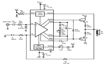
The LME49810 audio amplifier schematic is depicted in the accompanying circuit diagram. Based on the LME49810 datasheet, this component is a high-fidelity audio power amplifier driver intended for use in applications such as audio-video receivers, guitar amplifiers, powered studio...
This Wien bridge oscillator utilizes an incandescent lamp to stabilize its amplitude. The amplitude stabilization results in a low distortion output and supports multiple frequencies. The Wien bridge oscillator is a type of electronic oscillator that generates sine waves. It...