
Wien Bridge Oscillators

The Wien Bridge Oscillator is a well-known electronic circuit used to generate sine waves. It operates on the principle of balance between resistive and reactive components within its feedback loop. In this configuration, the filament lamp serves as a variable resistor, whose resistance changes with temperature, thereby influencing the gain of the op-amp. The circuit typically consists of an op-amp, a feedback network including the filament lamp and resistors, and capacitors to establish the desired frequency of oscillation.
The design requires careful selection of the lamp and resistors to ensure that the gain is appropriately managed. During the initial phase of oscillation, the gain must be sufficiently high to initiate oscillations, while it must stabilize at a lower value to maintain a steady output. The operational amplifier must be configured in a non-inverting configuration to achieve the necessary phase shift for sustained oscillation.
The feedback network is critical, involving a combination of resistors and capacitors that set the frequency of oscillation according to the Wien Bridge formula. The circuit's stability and output quality can be affected by the characteristics of the filament lamp, necessitating the creation of a resistance-temperature graph for optimal performance. The practical implementation of this oscillator may require tuning and adjustments to accommodate variations in component tolerances and supply voltages, ensuring that the output remains a clean sine wave suitable for various applications, including audio signal generation and testing purposes.A basic Wien Bridge Oscillator using a filament lamp with an op amp. It is a property of filament lamps that the resistance of the tungsten filament increases in a non-linear manner as the filament heats up. The lamp in Fig. 3. 4. 1 is connected in the negative feedback potential divider that sets the gain of the non-inverting ampli
fier. The gain of the amplifier is set by: Therefore the greater the resistance of the lamp the lower the amplifier gain. By choosing a suitable lamp, the gain of the amplifier can be automatically controlled over an appropriate range.
Usually a lamp with a maximum current flow of around 50mA or less is used, to give an initial gain of more than 3 as the oscillator starts, falling quickly to 3 as the lamp heats up. Hewlett`s original 1939 design used a high voltage vacuum tube (valve) and relatively large lamp, with modern low voltage semiconductors however, it is not easy to find suitable filament lamps that have a suitable voltage range and a low enough current to avoid overloading the amplifier, although useful lamps can still be found, usually of the wire ended T1 or grain of rice` types but even they are becoming more difficult to find in component suppliers catalogues, as LED types become more popular for low voltage lighting.
Fig. 3. 4. 2 shows a low current filament lamp designed to work from 5V at 45mA, and Fig. 3. 4. 3 is a graph taken from a typical example, showing how its positive temperature coefficient resistance varies with voltage. (Note that resistance without any temperature dependant characteristics would be a straight line). The useful area of the lamp characteristic, where the largest change in resistance occurs is shaded green, the oscillators amplitude is stabilised by making use of this area.
However, because filament lamps are not made as electronic control devices, manufacturers do not usually provide graphs such as that in Fig. 3. 4. 3 so, when using a lamp as a stabilising component it is necessary to first construct a graph for the lamp to be used, and decide on the active area.
The gain of the amplifier in Fig. 3. 4. 1 depends on the ratio of the values of the feedback resistor R3 and the lamp. For oscillations to start, the amplifier gain needs to be greater than 3, but to work correctly after the initial start up the gain must be 3. Using the formula: This requires the lamp to be half the resistance of the feedback resistor R3 to provide the necessary gain of 3, but slightly less than twice the resistance of R3 at start up.
To find a value for R3 that will give the correct amount of gain at start up and during oscillation, its value should be slightly greater than twice the value of the lamps resistance at the lower end of the green shaded area (i. e. 2 x 30 © = 60 ©) to give a gain >3, but no greater than twice the value of the lamp`s resistance at the upper limit of its useful slope (i.
e. 2 x 75 = 150 ©), the gain should then stabilise at 3, with the oscillator providing an undistorted sine wave output. To obtain an undistorted output at a specific amplitude, it is useful to initially use a variable resistor of about 1k © in place of the feedback resistor.
Varying the resistor will show the limits between the greatest amplitude before distortion and the smallest amplitude for stable operation. The resistance of the variable control can then be measured find the value of feedback resistor that provides a stable and undistorted wave of acceptable amplitude.
In a test circuit, built using a LM324 op amp with a supply voltage of ±9V to ±12V a value of 68 © to 82 © proved ideal. These calculations will almost inevitably produce values that do not match available components so it will be necessary to choose a preferred value closest to the calculated one.
It may be possible to make up an odd value from two preferred values to get closer to the required frequency, remembering that componen 🔗 External reference
Related Circuits
The HandyBoard operates both pads using the positive supply from the battery. When one of the motors is intended to turn, the HandyBoard activates the corresponding pin to 0V. The voltage difference between the two pads causes the motor...
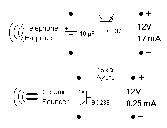
In order to generate a single note you may try these simple circuits. With only three components you may implement some basic buzzers. You need a telephone earpiece for the first circuit. Any old telephone set has got one...

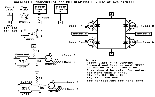
The 10A H-Bridge Motor Controller circuit appears straightforward, but several critical aspects should not be overlooked. The primary components utilized in the circuit include the TIP147, TIP142, and 2N2222 transistors. The power supply circuit operates at +12V, which is...
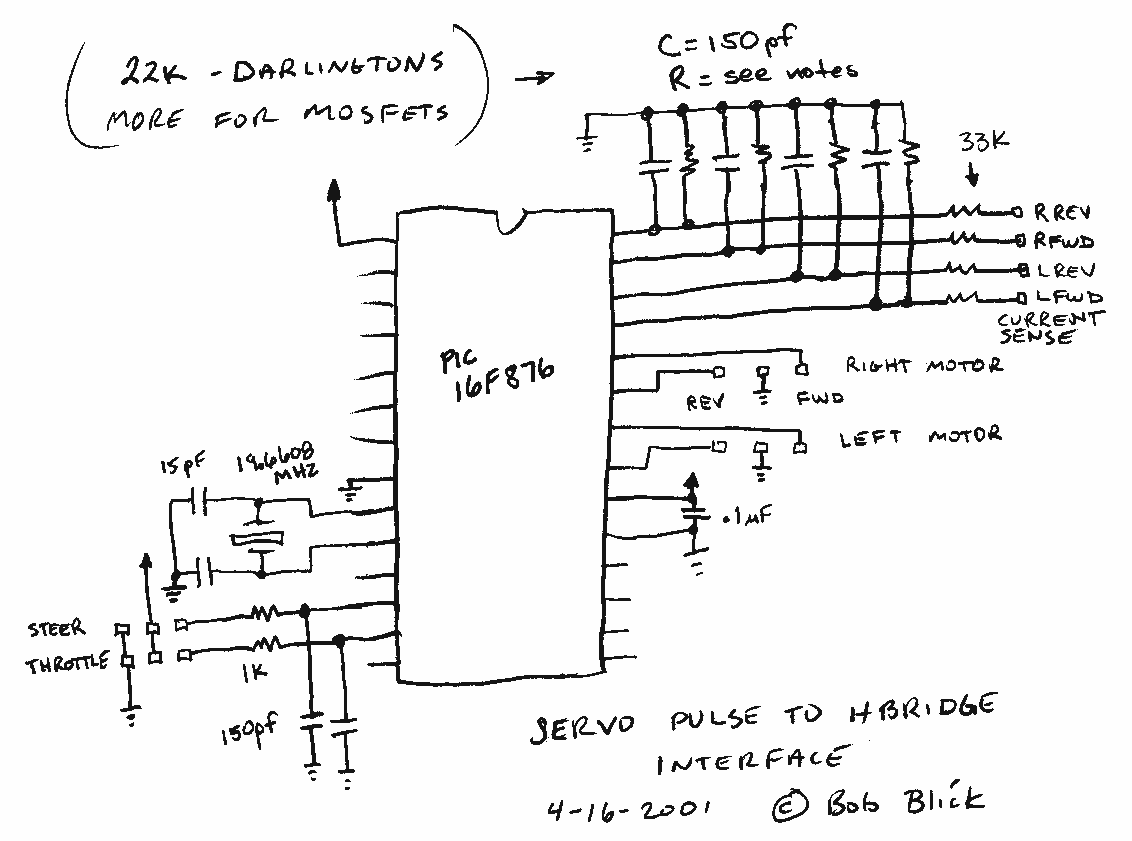
The interface uses a PIC16F876 microcontroller and not much else. It performs channel mixing, current limiting, and noise rejection. Push the stick forward, both motors move forward, move the stick to the left and the robot moves left. It...
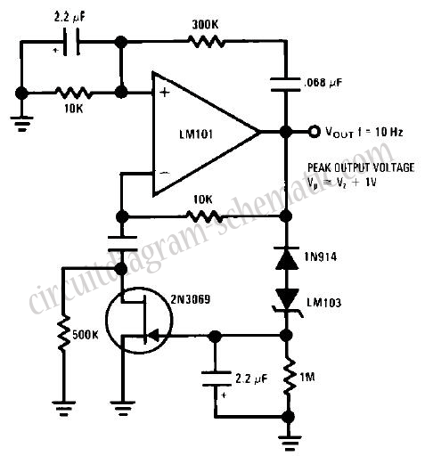
This circuit is a Wien Bridge Sine Wave Oscillator. The primary challenge in generating a low distortion, constant amplitude sine wave is to achieve the appropriate loop gain in the amplifier. By utilizing the 2N3069 JFET as a variable...
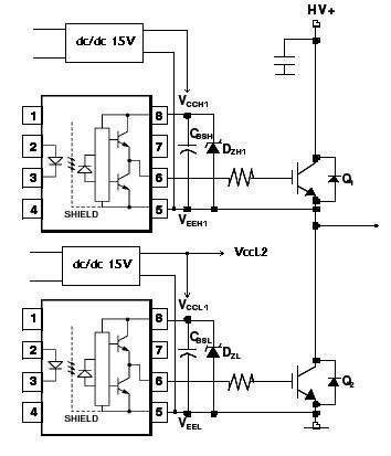
An H-bridge circuit has been developed utilizing four floating gate drivers and four insulated gate bipolar transistors (IGBTs). The attached schematic illustrates one half of the H-bridge configuration. The circuit operates effectively, but there are additional considerations to address. The...