
Oscillators and Triggers
The circuit design utilizing transistors, particularly in oscillators, capitalizes on their ability to handle high frequencies and their compatibility with existing vacuum tube circuits. The multivibrator circuit, for instance, demonstrates how feedback mechanisms can effectively initiate oscillations, with the frequency determined by the reactive components in the circuit. The transition from vacuum tubes to transistors not only enhances performance but also allows for more compact designs with greater efficiency. The grounding configurations play a crucial role in determining the phase relationships and overall functionality of the circuit, making the understanding of these principles essential for effective circuit design. The advantages of transistors, such as improved frequency response and higher output resistance, continue to drive innovation in electronic circuit design, leading to more robust and versatile applications in modern electronics.Transistors are finding new and ever-increasing uses. Some of the circuits in which transistors are being applied are well-known through prior employment in conjunction with vacuum tubes. The applications shown in the chapters which follow illustrate some of the more unique ways in which to take advantage of the desirable properties of transistors
. The circuits that are described are practical, have been built, tested, and are now in use. THOUGH transistors generally demand their own circuitry, there are some good vacuum-tube circuits that function nicely when transistors are substituted. As the phase relations of a grounded-emitter transistor resemble those of a grounded-cathode vacuum tube, it is possible to use junction transistors for vacuum tubes in most oscillator circuits.
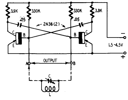
The multivibrator and the two-terminal sine-wave generator perform well with junction transistors, with the transistorized two-terminal L-C having a great advantage over other transistor oscillators. As with vacuum tubes, the circuit oscillates on higher frequencies than single-transistor oscillators with the same components.
While transistors must be selected for other oscillators, most transistors, even those not oscillating in single oscillators, work well on rf in this circuit. The multivibrator is in principle a two-stage R-C coupled amplifier (Fig. 501). The output voltage of the second tube is fed back to the grid of the first tube. Because of this feedback the circuit starts to oscillate at a frequency determined by the time constants of R and C.
The circuit will also oscillate if you substitute an element with similar amplifying and phase-shift relations in place of the vacuum tubes. Before getting into further circuitry, let`s discuss the principle of analogy. Fig. 502 shows a junction transistor and a vacuum-tube triode in common-emitter and common-cathode connections.
The symbols e, c and b represent the emitter, collector and base, respectively. We can immediately draw an analogy between the terminals of the two devices: The emitter corresponds to the cathode, the collector to the plate, the base to the grid. The analogy may be extended by noting that an ac signal undergoes a phase reversal between input and output electrodes ”base and collector for the transistor, grid and plate for the tube.
If you make the grid of the vacuum tube more positive, plate current increases and as the plate current increases the plate becomes less positive due to the voltage drop across the load resistor. Thus, all "mountains" of a sine wave applied to the grid are trans ¬formed into "valleys" of the anode voltage.
Now look at the grounded-emitter circuit (Fig. 503) of a p-n-p junction transistor. If the base is made more negative with respect to the emitter, col ¬lector current increases and the voltage drop across the load resistor causes the collector to become more positive. So, a sine wave is "turned over" the same as with a vacuum tube, a grounded-emitter transistor producing the same 180 ° phase shift as a grounded cathode vacuum tube.
Fig 503 shows how the grounded-emitter circuit of a junction transistor corresponds to the grounded-cathode circuit of the vacuum tube. There are, of course, certain differences between the two. Whereas the grid is returned to a negative source and Ig is zero for normal operation, the base return is positive (in transistors with a positive collector) and I is not zero.
This means that the input resistance of the transistor is not infinite, as is the tube`s, but has a finite, actually low, value. The magnitudes of the output resistances are also dissimilar, the transistors` being much higher than that of the tube.
However, as alpha, the ratio of a change in Ic to a change in Ie, increases to unity, the differences decrease and the analogy becomes closer. The input resistance of the transistor rises and its output resistance drops correspondingly. An importan 🔗 External reference
Related Circuits
One of the significant challenges in designing vacuum-tube oscillators is maintaining a constant frequency despite mechanical vibrations, temperature fluctuations, voltage variations in the supply lines, and changes in the load power drawn from the circuit. The effects of variable...
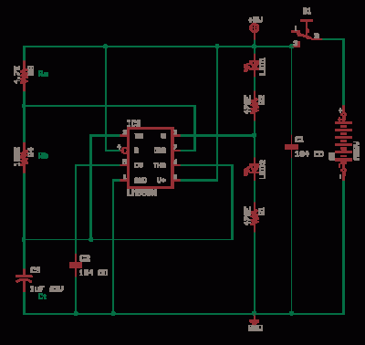
The LM311 is a comparator that operates from a single 5V supply or dual supplies, with an input current of 150 nA and an output drive capability of 50 V and 50 mA. It features a TTL-CMOS compatible output....
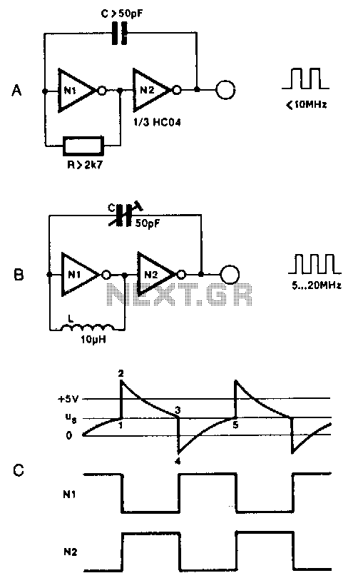
Two inverters, one resistor, and one capacitor are sufficient to create an HC(T)-based oscillator that operates reliably up to approximately 10 MHz. The use of two HC inverters results in a fairly symmetrical rectangular output signal. In this configuration,...
A brief note explaining the process of substituting crystal and ceramic resonator clock circuits with silicon oscillators, while emphasizing the technical benefits these devices provide in microcontroller clock applications. Silicon oscillators serve as an effective alternative to traditional crystal and...
Unlike conventional small-signal methods, employing large-signal, time-domain design techniques facilitates the development of low-noise grounded-base oscillators suitable for VHF/UHF applications. The implementation of large-signal, time-domain design techniques in the creation of grounded-base oscillators represents a significant advancement in the field...
Online Electronics Course covering the Science of Radio Frequency Engineering, including topics such as Electronics, Microwave Technology, Waveguides, Antennas, Tubes, Historical Context, Klystrons, Magnetrons, Traveling Wave Tubes (TWT), Internet of Things (IoT), Klystrodes, Broadcast Equipment, and Repair Techniques. The online...
Warning: include(partials/cookie-banner.php): Failed to open stream: Permission denied in /var/www/html/nextgr/view-circuit.php on line 713
Warning: include(): Failed opening 'partials/cookie-banner.php' for inclusion (include_path='.:/usr/share/php') in /var/www/html/nextgr/view-circuit.php on line 713