
Oscillators 5

The 555 astable oscillator generates a square wave output at pin 3, which drives two LEDs: LED1 illuminates when pin 3 is low, while LED2 lights up when pin 3 is high. The 555 can source (LED2) or sink (LED1) up to 200 mA, and it can also drive a small motor or lamp with diodes added for protection against inductive kickback. By varying resistors Ra, Rb, and capacitor Ct, one can observe changes in frequency, period, and duty cycle, which are calculated using the following formulas: T1 = 0.693 (Ra + Rb) * Ct (charge time of Ct) and T2 = 0.693 (Rb * Ct) (discharge time).
This circuit also includes an unregulated power supply suitable for low-power applications, which can be regulated using zener diodes or small regulators like the 78L05. The transformer can be hand-wound using a mini ferrite pot core, with a requirement for 1 kV isolation. The dot polarity of transformer TR1 must be observed to ensure proper oscillation and output. A fast recovery diode is recommended, such as the 1N4148 for currents under 100 mA. The transformer specifications include a primary winding of 20-20 turns and a secondary winding of 60-60 turns, with wire gauge (SWG/AWG) selected based on the current design requirements. Any fast-switching transistor can be employed.
This circuit is based on an application note from Exar, where the frequencies are fixed by IC1 and IC2, with P1 controlling the duty cycle. R and C values need to be computed to achieve the desired specifications, as detailed in the LM555 datasheet. This design encourages innovation beyond mere replication, suggesting that users should study the circuit thoroughly, experiment, and consider designing a PCB based on the provided Eagle circuit for practical learning.LM311 is a comparator, It operates from single 5V supply or dual supplies, input current 150 nA, 50 V-50 mA output drive capability. TTL-CMOS compatible output. The Output is open collector so it can sink current but cannot source, a totem pole output can source and sink.
In this Circuit R2 is the source or pull-up. The Output being high or low depends on which input is more dominant or positive. If + or non-inverting input is more positive than the inverting input then output of LM311 is high impedance or high Z as output transistor of LM311 is turned Read More 74HCU04 is a chip that was made for this purpose, HCT may not work for such a circuit. C1 and C2 can go to upto 33pF and R2 can be increased to make R2 * C2 = t. Time constant much less than the period T of the crystal T = 1/F. This is to remove higher frequency components in the Oscillator. The circuit above is a parallel resonant oscillator circuit. The Crystal works by the piezoelectric principle, piezo means pressure. The electric field causes the impedance of the crystal to change. The LP Record Player needle is the Read More The 555 Astable oscillator gives a square wave output at pin 3, The output drives two LEDs, LED1 lights up when pin 3 is low and LED2 when pin 3 is high.
de_gads_top The 555 can source (LED2) or Sink (LED1) upto 200mA. It can even drive a small motor or lamp with diodes added to protect from inductive kickback. Vary Ra, Rb and Ct and see the change of frequency, period and duty cycle. These are the formulae used by 555. T1 = 0. 693 (Ra + Rb) * Ct charge time of Ct T2 = 0. 693 (Rb * Read More This is a unregulated supply for low power circuits. You may be able to regulate the outputs with zeners or small regulators like 78L05. The transformer can be hand wound in a mini ferrite pot core. you can use 2N2222 or any other fast transistor. The transformer should have 1KV isolation. The dot polarity of TR1 should be properly observed, else it may fail to oscillate or give output. Diode should be fast recovery type, for less than 100mA use 1N4148. transformer, pri-20-20, sec-60-60, a SWG-AWG to suit the current you design for, any fast switching transistor would work, no Read More This circuit is based on a very old application note from exar, in this the frequency is fixed by IC1 and IC2 -P1 controls the duty cycle. you need to compute the R and C values to get what you need, LM555 data sheet. You have to study the circuit and do something more innovative perhaps, just copying is ok for learning but it will get you nowhere, so learn and then innovate, the eagle circuit is given below so you can learn by editing it, also design a PCB with it, and you can even make a PCB at Read More
🔗 External reference
Related Circuits
A simple network design is a key feature of the Pierce circuit, as illustrated by these 1-MHz oscillators. Operating the crystal slightly above resonance requires only one high-gain transistor stage. Operating it exactly at series resonance requires an additional...
Transistors are increasingly being utilized in various applications. Many circuits employing transistors have been developed based on previous designs that used vacuum tubes. The following chapters present unique applications that leverage the advantageous properties of transistors. The described circuits...
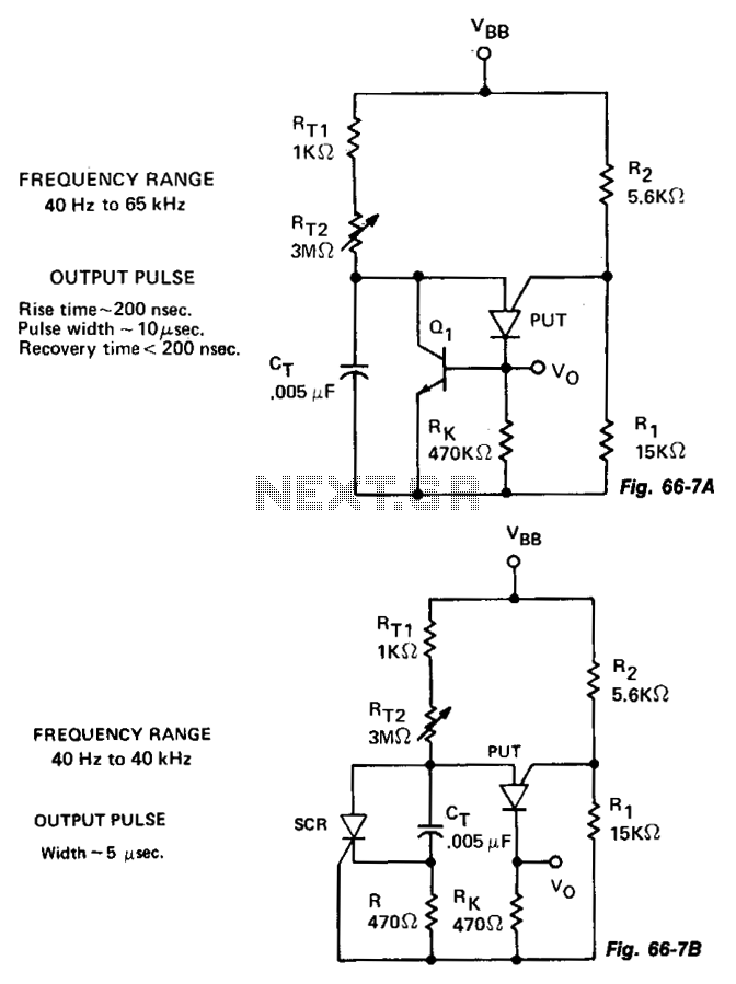
The variable oscillator circuit incorporates active components to discharge the timing capacitor CT, as illustrated in Fig. 66-7A. An alternative method is presented in Fig. 66-7B. The variable oscillator circuit is designed to generate oscillating signals with adjustable frequency characteristics....
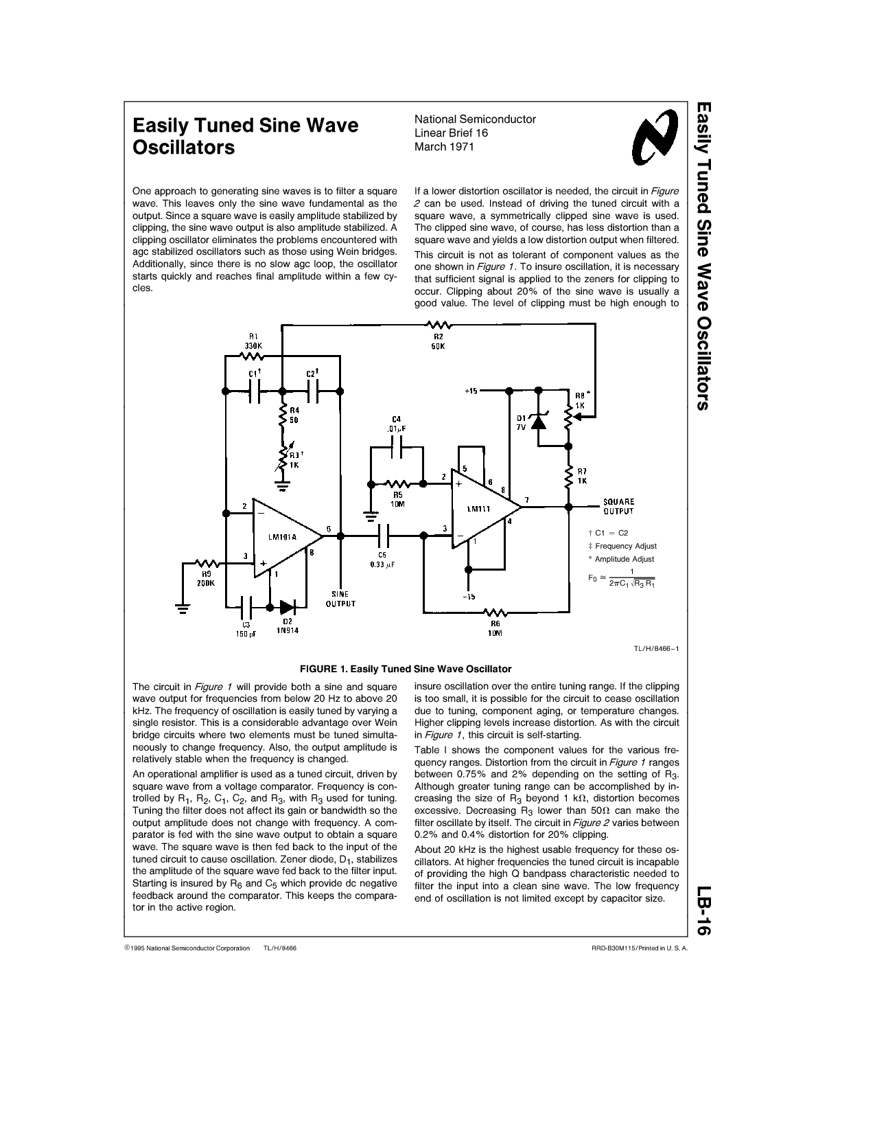
One approach to generating sine waves is to filter a square wave. This leaves only the sine wave fundamental as the output. If a lower distortion oscillator is needed, the circuit in Figure 2 can be used. Instead of...
The schematic illustrates the division of a crystal oscillator signal by the crystal frequency to achieve a precise 1-second time base with an accuracy of 0.01%. Two cascaded 12-stage counters (CD4040) create a 24-stage binary counter, with specific bits...
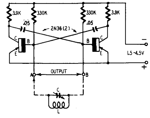
The transformer OCL and capacitor C1 create a tank circuit, which is coupled with sufficient turns to drive the grid in the lower left-hand winding. The output circuit is connected through a separate winding. For optimal waveform characteristics in...