
Receiver for 50 khz optical transmitter
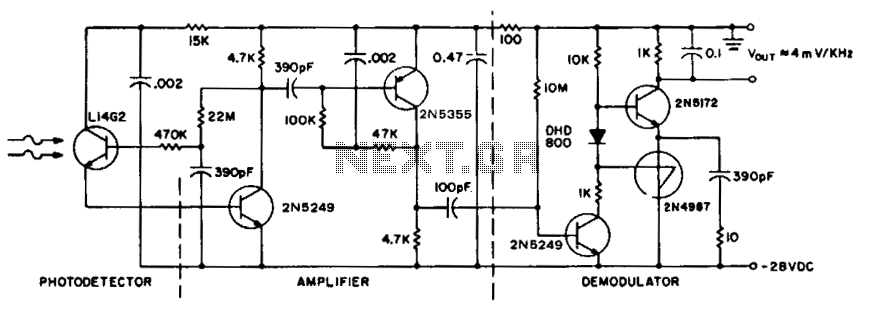
The described receiver circuit is engineered to optimize performance in environments where signal integrity is paramount. The L14G2 detector serves as the initial signal processing element, converting incoming optical signals into electrical currents. This is followed by two gain stages that amplify the signal while maintaining a careful balance to preserve the signal-to-noise ratio. The FM demodulator, adapted from a tachometer design, processes the amplified signal to recover the frequency-modulated information, allowing for accurate measurement and interpretation of the received data.
Incorporating additional stages of stabilized gain with AGC can enhance the sensitivity of the receiver. AGC automatically adjusts the gain of the amplifier stages based on the incoming signal strength, ensuring optimal performance across varying signal conditions. This feature is particularly beneficial in applications where signal levels fluctuate significantly.
Alternatively, for applications where cost is a critical factor, the use of an H23A1 emitter-detector pair can simplify the design while still providing adequate performance. This approach may involve the elimination of one or more amplifier stages, which can lead to a more compact and cost-effective solution, albeit at the expense of some sensitivity.
Furthermore, in scenarios where the output voltage is susceptible to noise or interference, additional filtering may be required. This can be accomplished through the implementation of low-pass filters or other filtering techniques that help to smooth out the output signal, ensuring that the final output is clean and representative of the intended measurement.
Overall, the design of this receiver circuit must carefully consider these various factors to achieve a reliable and efficient performance suitable for its intended application.For maximum range, the receiver must be designed in the same manner as a radio receiver front end, since the received signals will be similar in both frequency component and in amplitude of the photodiode current. The major constraint on the receiver performance is signal to noise ratio, followed by e.m. shielding, stability, bias points, parts layout, etc. These become significant details in the final design. This receiver circuit consists of a L14G2 detector, two stages of gain, and a FM demodulator which is the tachometer circuit, modified to operate up to 100 kHz.
Better sensitivity can be obtained using more stages of stabilized gain with AGC, lower cost and sensitivity may be obtained by using an H23A1 emitter-detector pair and/or by eliminating amplifier stages. For some applications, additional filtering of the output voltage may be desired. 🔗 External reference
Related Circuits
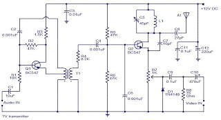
Here is a simple yet very useful circuit which can be used to eavesdrop on a telephone conversation. The circuit can also be used as a wireless telephone amplifier. One important feature of this circuit is that the circuit...
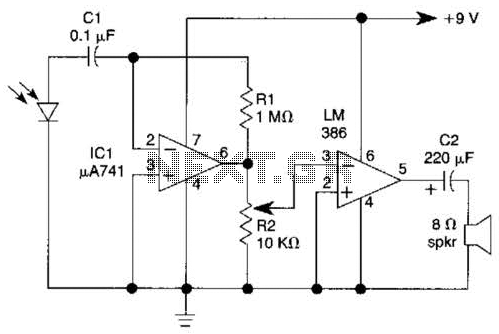
This light-wave receiver comprises a 741 operational amplifier functioning as a preamplifier and an LM386 operational amplifier serving as a power amplifier. The gain control is managed by a potentiometer labeled R2. Various types of detectors can be utilized...
The camera is oriented to look out the side of the rocket during launch and downward during descent on the parachute. An optional external mirror can be added to enable the camera to look down during lift-off. The transmitter...
The diagram illustrates the principle circuit of a radio control car receiver. Important notes include the selection of transistor Q1, which is specified as either 1815 or 9018, along with the bias resistor R1, which has values of 240K...
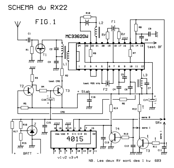
This receiver weighs about 6 g, used in 41 and 72 MHz, met a great success with readers of the magazine. The RX22 is the subject of these lines is improved RX20. Adding a preamp-HF improving sensitivity. Establishment of...
The single-813 crystal oscillator transmitter, designed by RCA, was showcased in an advertisement on the back page of a 1938 "QST" magazine and published in the RCA HamTips bulletin, volume 1, number 4, dated December 1938. This transmitter delivers...