
1 Hz Sine wave generator

No description available.
Related Circuits
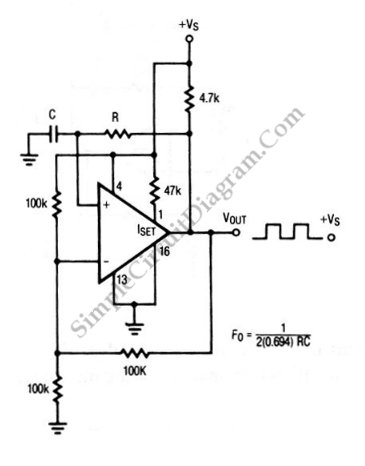
The circuit depicted in this schematic diagram is a square-wave oscillator circuit. The primary component of this oscillator circuit is the LP165/365 comparator. The square-wave oscillator circuit utilizes the LP165/365 comparator to generate a continuous square wave output. The...
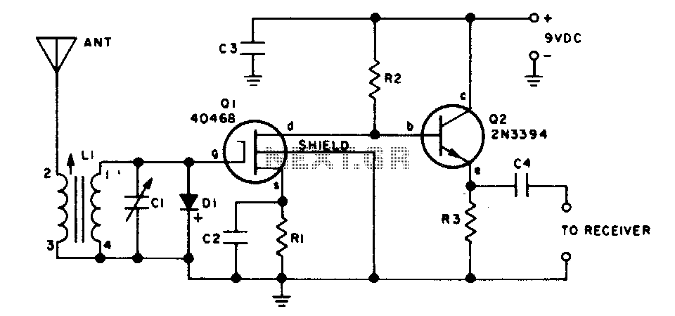
This two-transistor preselector provides up to 40 dB gain from 3 to 30 MHz. Q1 (MOSFET) is sensitive to static charges and must be handled with care. The two-transistor preselector circuit is designed to amplify signals within the frequency range...
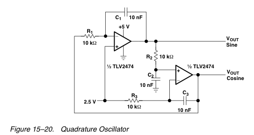
After disappointing results with a transformer-based component tester, there is an interest in generating a ±10 V sine wave at approximately 50 Hz using minimal components. While an ATmega microcontroller could achieve this, it may be considered excessive, requiring...
The interval between rings can be adjusted by changing the value of the 1 Meg resistor. A 70 volt, 30 Hz ringing voltage is generated from the 120 volt side of a small 12.6 VAC power transformer (Radio Shack...
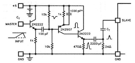
The UC3842, UC3843, UC3844, and UC3845 series of oscillators can generate synchronization pulses without requiring numerous external components. The following circuit illustrates the Sync Pulse Generator Circuit Diagram for the UC3842/3/4/5. This sync pulse circuitry is capable of operating...
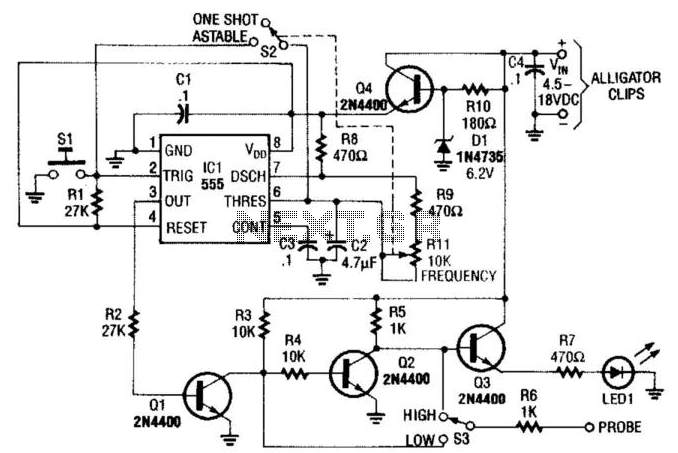
This pulse generator is constructed using a 555 timer integrated circuit (IC) and can be integrated into a probe for logic troubleshooting. Resistor R1 controls the frequency, providing a range of approximately 5 to 200 Hz. Capacitor C2 can...