
Digital Sine Wave Oscillator
The little generator with the AT90S8515 worked well enough for that experiment, that I decided to build up a version that uses the ATTINY2313 or AT90S2313 (I tested the firmware on both chips) so the 1 kHz sine wave generator would be available for some future experiments that I am planning.
At this point, you might wonder at my choice of an AT90S2313 instead of the ATTINY2313. I still have lots of AT90S2313's and intend to use them where I can. There is not much of a market for obsolete controllers. Code is provided for the ATTINY2313/AT90S2313 and the ATMEGA8515/AT90S8515. The ATTINY2313 hex file was tested on both the ATTINY2313 and the AT90S2312, while the AT90S8515 hex file was only tested on an AT90S8515. The AT90S8515 hex file is fully expected to run on the ATMEGA8515 without any problems, provided that the ATMEGA8515 is operated in the AT90S8515 compatibility mode (see below). The DAC is made up of 9 each 20 k Ohm and 7 each 10 k Ohm resistors, connected as an R-2R ladder network. The output of the DAC shunted by a voltage divider, whose resistance is 2.8 k Ohms, which simultaneously decreases the amplitude of the the sine wave to about 900 millivolts. Without the voltage divider (6.8k and 4.7K, the output would be nearly 5 volts peak-to-peak.) An integrated circuit DAC would have worked just fine, and I have some laying around, but somehow, it was more satisfying to make my own DAC with resistors.
Take note, that I used 5% resistors in the DAC, and if the resistors had been at the edge of their specification, the monotonicity would have been about 4 /12 bits. Fortunately, the resistors that I have bothered to measure are much closer to their specified values than this. Even more important, is that in this application, particularly when only generating a relatively coarse 32 values sine wave, a little error in monotonicity only results in as slight increase in harmonic content, and the low pass filter takes care of it.
Spurious signals in the output were about 40 db below the 1 kHz carrier in the original circuit, but a I added a capacitor to the 2313 circuit that is also in parallel with the output of the DAC forms an approximately 1.5 kHZ single pole low pass filter, which is enough to bring the spurious signals to about 50 db below the 1 kHz sine wave, while not affecting the amplitude of the 1 kHz signal much at all.
The reason its nice that the low pass filter does not affect the amplitude of the 1 kHz signal is because this reduces the amplitude's dependency on the corner frequency of the filter. The capacitor could drift quite a bit and not affect the amplitude of the 1 kHz signal much because its not affecting the amplitude much in the first place. If I had placed the corner frequency much lower, it would have more of an affect. As it happens, the .047 uf capacitor that I used in the filter is made with polypropylene, which has a temperature coefficient of about 0.02% per degree C around room temperature.
A voltage follower buffers the signal, which is AC coupled to the output through a 100 uf capacitor. A second output from the buffer drives an inverting amplifier that has a gain adjustment. The second amplifier can be adjusted to provide a calibrated 1 volt P-P output.
The circuit comprises a microcontroller-based signal generator utilizing either the AT90S2313 or ATTINY2313 microcontroller. The microcontroller generates a 1 kHz sine wave signal by utilizing a digital-to-analog converter (DAC) formed by an R-2R resistor ladder network. The ladder consists of nine 20 kΩ resistors and seven 10 kΩ resistors, which create a binary-weighted output voltage. The output of the DAC is then passed through a voltage divider to reduce the amplitude to approximately 900 mV, effectively ensuring that the output does not exceed the desired voltage levels.
A single-pole low-pass filter is implemented using a capacitor connected in parallel with the DAC output, which helps to attenuate unwanted high-frequency spurious signals. The filter is designed to have a cutoff frequency around 1.5 kHz, which effectively reduces spurious signals to about 50 dB below the 1 kHz sine wave, ensuring a clean output signal. The capacitor used in the filter is a polypropylene type, known for its stability and low temperature coefficient, which contributes to the reliability of the sine wave output.
To buffer the signal and provide isolation from the load, a voltage follower is employed. This stage is AC coupled to the output via a 100 µF capacitor, ensuring that any DC offset is eliminated. Additionally, a second output from the voltage follower feeds into an inverting amplifier, which allows for gain adjustment. This amplifier can be calibrated to provide a precise 1 V peak-to-peak output, useful for various experimental setups.
Overall, this circuit design effectively combines analog and digital techniques to produce a stable, low-distortion 1 kHz sine wave signal suitable for a variety of applications in experimental electronics.If found myself in need of a 1 KHz signal source for an experiments. My function/sweep generator was needed as a pulse generator for the same experiment, so I went though my junk box, looking for circuits from long ago that might fill the need, but found nothing useful. I had a board with an AT90S8515 and an 8 bit resistor ladder network on it, which serves as a DAC (digital to analog converter), so I thought "This will be easy." and sat down to write the code.
Since I wrote it in C rather than assembly, writing the code took much longer than I expected, but in the end, I managed to get it to do what I wanted it to do, and I fixed the typographical errors. The little generator with the AT90S8515 worked well enough for that experiment, that I decided to build up a version that uses the ATTINY2313 or AT90S2313 (I tested the firmware on both chips) so the 1 kHz sine wave generator would be available for some future experiments that I am planning. At this point, you might wonder at my choice of an AT90S2313 instead of the ATTINY2313. I still have lots of AT90S2313's and intend to use them where I can. There is not much of a market for obsolete controllers. Code is provided for the ATTINY2313/AT90S2313 and the ATMEGA8515/AT90S8515. The ATTINY2313 hex file was tested on both the ATTINY2313 and the AT90S2312, while the AT90S8515 hex file was only tested on an AT90S8515.
The AT90S8515 hex file is fully expected to run on the ATMEGA8515 without any problems, provided that the ATMEGA8515 is operated in the AT90S8515 compatibility mode (see below). The DAC is made up of 9 each 20 k Ohm and 7 each 10 k Ohm resistors, connected as an R-2R ladder network.
The output of the DAC shunted by a voltage divider, whose resistance is 2.8 k Ohms, which simultaneously decreases the amplitude of the the sine wave to about 900 millivolts. Without the voltage divider (6.8k and 4.7K, the output would be nearly 5 volts peak-to-peak.) An integrated circuit DAC would have worked just fine, and I have some laying around, but somehow, it was more satisfying to make my own DAC with resistors.
Take note, that I used 5% resistors in the DAC, and if the resistors had been at the edge of their specification, the monotonicity would have been about 4 /12 bits. Fortunately, the resistors that I have bothered to measure are much closer to their specified values than this.
Even more important, is that in this application, particularly when only generating a relatively coarse 32 values sine wave, a little error in monotonicity only results in as slight increase in harmonic content, and the low pass filter takes care of it. Spurious signals in the output were about 40 db below the 1 kHz carrier in the original circuit, but a I added a capacitor to the 2313 circuit that is also in parallel with the output of the DAC forms an approximately 1.5 kHZ single pole low pass filter, which is enough to bring the spurious signals to about 50 db below the 1 kHz sine wave, while not affecting the amplitude of the 1 kHz signal much at all.
The reason its nice that the low pass filter does not affect the amplitude of the 1 kHz signal is because this reduces the amplitude's dependency on the corner frequency of the filter. The capacitor could drift quite a bit and not affect the amplitude of the 1 kHz signal much because its not affecting the amplitude much in the first place.
If I had placed the corner frequency much lower, it would have more of an affect. As it happens, the .047 uf capacitor that I used in the filter is made with polypropylene, which has a temperature coefficient of about 0.02% per degree C around room temperature. A voltage follower buffers the signal, which is AC coupled to the output through a 100 uf capacitor. A second output from the buffer drives an inverting amplifier that has a gain adjustment. The second amplifier can be adjusted to provide a calibrated 1 volt P-P output. 🔗 External reference
Related Circuits
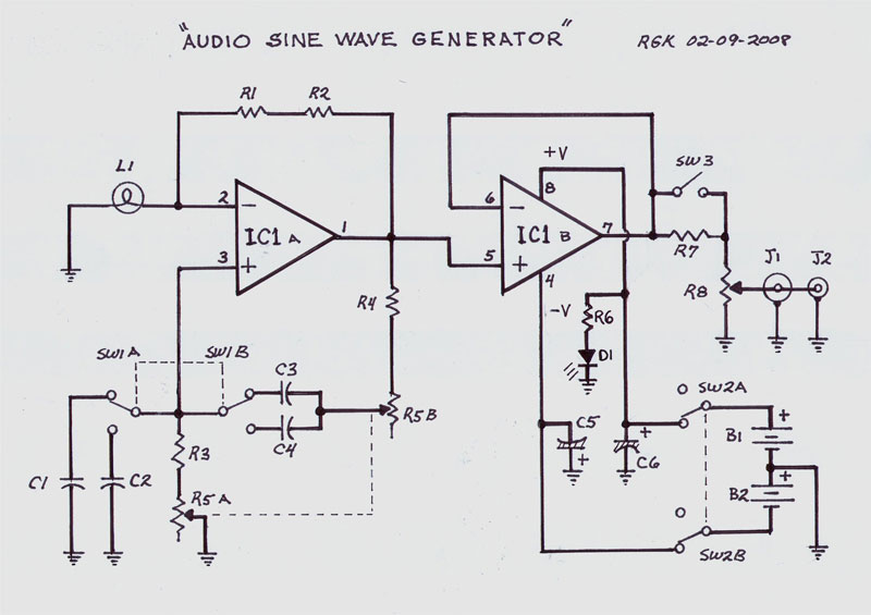
This single integrated circuit (IC) design is based on the Wien Bridge Oscillator, generating low distortion sine waves within a frequency range of 15 Hz to 22 kHz across two output voltage levels: approximately 0-250 mV and 0-2.5 Vrms....
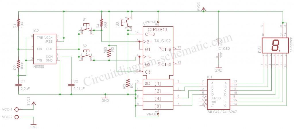
The digital scoreboard circuit is designed to display numerical values ranging from 0 to 9 on a 7-segment display. This display utilizes a common anode configuration. The digital scoreboard circuit operates by controlling a 7-segment display that utilizes a common...
This circuit allows for amplifier volume control without the need for a potentiometer, utilizing an IC DS1669. The operating voltage for this type of IC ranges from 4.5 volts to 8 volts; however, in this circuit, it is used...
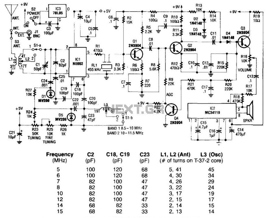
Using a Signetics NE602 in a varactor-tuned front end, the circuit of a shortwave receiver can be very simple and yet give high performance. This circuit also uses a ceramic filter as a sensitivity-determining device, two IF stages, AGC,...
Oscillator cores (cClappCore, cHartleyCore, cModifiedClappCore, and cModifiedColpittsCore) are compatible with simulation and measurement setups outlined by the Generic Oscillator Example. These core oscillator circuits are configured for low resistance loads (50 ohms is used for these four oscillator cores,...
The Colpitts oscillator has been redrawn for clarity. The inductor (L) is approximately 1.5 µH with 19 turns wound on a T50-6 core (yellow). The capacitor (C6) value has been determined experimentally, with a combination of 69 pF (using...