
Adjustable sine-wave audio oscillator
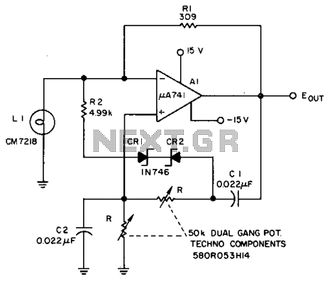
The described circuit employs a Lamp LI, which serves as a crucial component for stabilizing the loop gain in high-frequency applications. This stabilization is vital for maintaining consistent performance in oscillators and amplifiers, where variations in gain can lead to distortion and instability. The Lamp LI operates by providing a variable resistance that changes with the current, effectively modulating the gain based on the circuit's operational conditions.
In conjunction with the Lamp LI, resistors R2, CRI, and CR2 play a significant role in limiting the output signal to prevent clipping during low-frequency operations. Clipping occurs when the output signal exceeds the maximum amplitude that can be accurately represented, resulting in waveform distortion. By incorporating these components, the circuit can maintain linearity and fidelity in the output signal, particularly at lower frequencies where such issues are more pronounced.
The frequency adjustment range is notably improved from a ratio of approximately 3:1 to greater than 10:1. This enhancement allows for a broader spectrum of frequency outputs, making the circuit more versatile for various applications, including audio signal processing and precise frequency synthesis.
Furthermore, the use of diode limiting contributes to the overall waveform purity of the Wien bridge oscillator at low frequencies. Diode limiting acts as a protective mechanism that ensures the output signal remains within acceptable bounds, thereby preserving the integrity of the waveform. This feature is particularly important in applications where signal clarity and accuracy are paramount, such as in audio equipment and precision measurement devices.
In summary, the combination of the Lamp LI with the limiting components R2, CRI, and CR2, along with diode limiting, creates a robust circuit capable of delivering high-performance characteristics across a wide frequency range while maintaining waveform integrity. Lamp LI stabilizes the loop gain at higher frequencies while the limiting action of R2, CRI, and CR2 prevents clipping at low frequencies and increases the frequency adjustment range from about 3:1 to greater than 10:1. Waveform purity at low frequencies for a Wien bridge oscillator is enhanced by diode limiting. 🔗 External reference
Related Circuits
This simple and inexpensive crystal oscillator consists of one-third of a 7404 hex inverter, four resistors, and a crystal. The inverters are biased into their linear regions by resistors R1 to R4, while the crystal provides the necessary feedback....
The 3-channel audio mixer is a compact application utilizing transistor amplifiers. This audio mixer operates with a supply voltage of 9V DC, which can be provided by a battery. It is designed specifically for use as a portable amplifier....
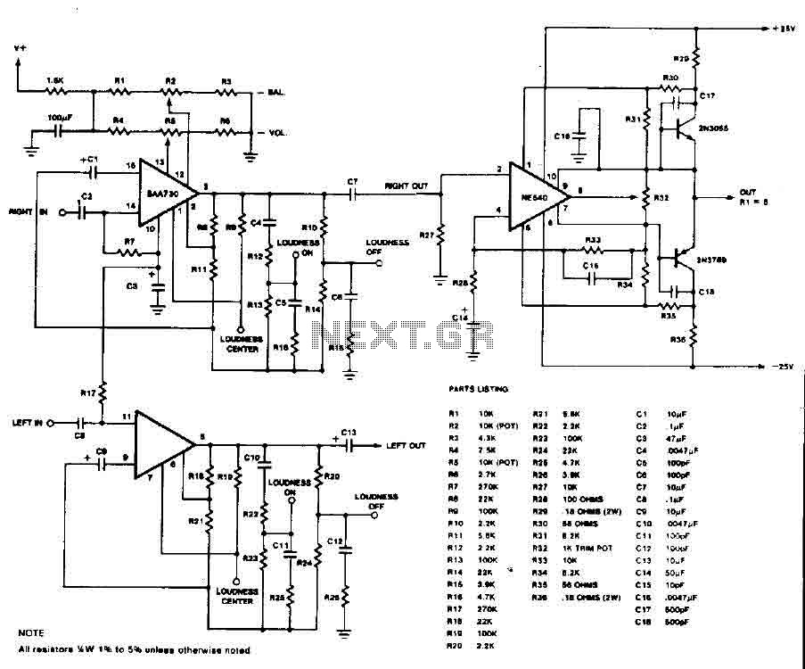
This circuit is an audio preamplifier that has balance, tone, and loudness controls. It should be suitable as an example of good design for audio applications. The audio preamplifier circuit utilizes the BAA730 and NE540 integrated circuits, which are...
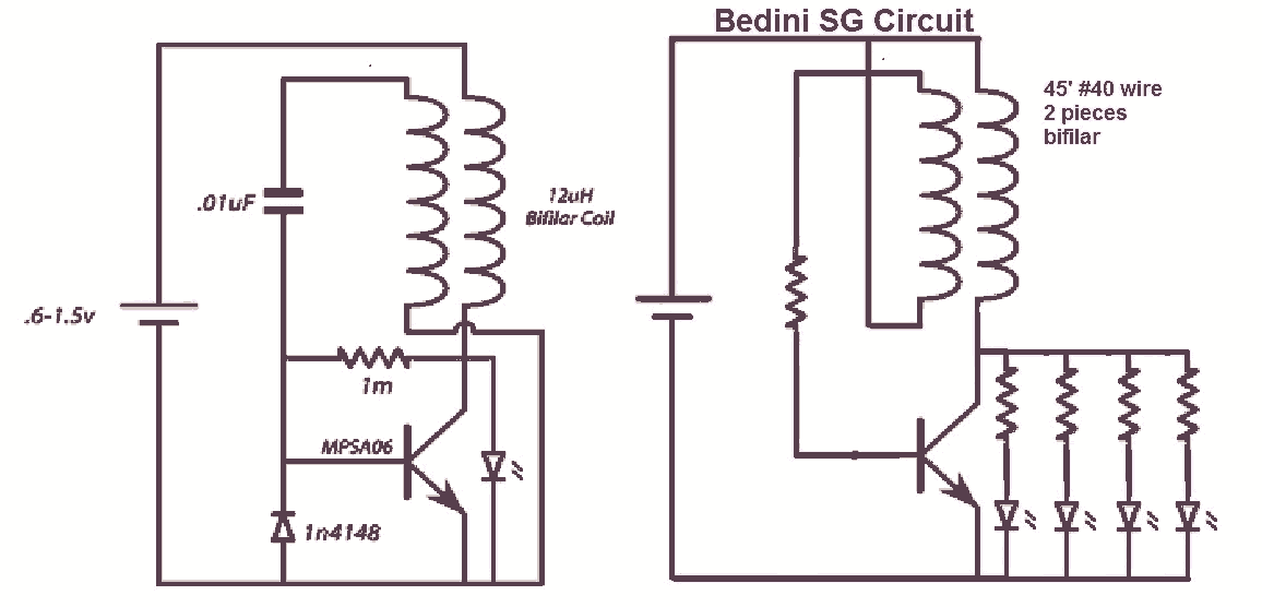
It would be beneficial to obtain schematics of the Joule Thief and Bedini oscillator circuit connections. This is an area that has not been previously explored. The schematic on the left was sourced from the Energetic Forum, while the...

A subsonic filter is primarily utilized in low-frequency technology. It is commonly employed to eliminate very low frequencies that can cause distortions in music recording or reproduction. A subsonic filter is an electronic circuit designed to attenuate frequencies below a...
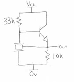
A ceramic resonator can be utilized to construct an oscillator. A single digital inverter can be employed to create a Pierce oscillator. To design a Pierce oscillator using a ceramic resonator and a digital inverter, the following components and configurations...