
Ceramic Resonator Oscillator Circuit

To design a Pierce oscillator using a ceramic resonator and a digital inverter, the following components and configurations are essential:
1. **Components**:
- **Ceramic Resonator**: This passive component provides the frequency stability and determines the oscillation frequency. The resonator should be selected based on the desired operating frequency.
- **Digital Inverter**: A single CMOS or TTL inverter, such as the 74HC04, will be used to create the oscillator circuit.
- **Capacitors**: Two capacitors (C1 and C2) are required, typically of equal value, to couple the resonator to the inverter and to set the gain and feedback necessary for oscillation.
- **Resistor (R)**: A resistor may be included in parallel with the inverter to help stabilize the oscillation and limit the current.
2. **Circuit Configuration**:
- Connect the output of the inverter to one terminal of the ceramic resonator.
- The other terminal of the resonator should be connected to ground.
- Place the two capacitors (C1 and C2) in series with the resonator, connecting one capacitor to the inverter input and the other to ground.
- Optionally, a resistor can be connected in parallel with the inverter to provide feedback stability.
3. **Operation**:
- When power is applied, the inverter will initially produce a low output, allowing the resonator and capacitors to charge. Once the voltage across the resonator reaches a certain threshold, the inverter output will switch high.
- This feedback mechanism creates a positive feedback loop, causing the inverter to toggle and generate a square wave output at the resonator's fundamental frequency.
- The frequency of oscillation can be adjusted by changing the values of the capacitors or selecting a resonator with a different frequency rating.
4. **Applications**:
- The Pierce oscillator is widely used in clock generation for microcontrollers, frequency synthesis, and other timing applications due to its simplicity and stability.
This configuration allows for a compact and efficient oscillator design suitable for various electronic applications. Proper attention to component selection and circuit layout will ensure optimal performance of the oscillator.I am looking to build a oscillator from a ceramic resonator. I know that a single digital inverter can be used to form a Pierce oscillator (hundreds.. 🔗 External reference
Related Circuits
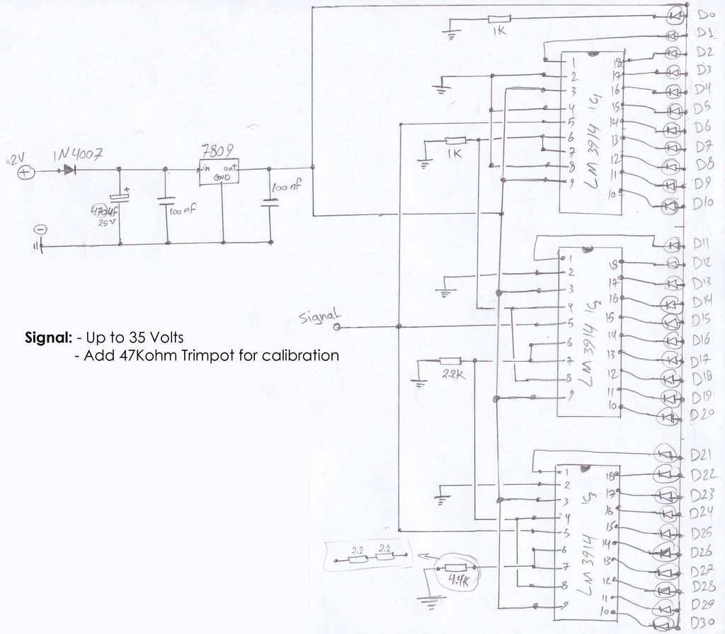
The circuit schematics operate at 12 Volts, sourced from a car battery. The ground connection is tied to the car chassis, while the signal is received from a sensor connected to a stepper motor. The No. 5 pin of...
The working principle involves two pairs of photoelectric detection devices installed in the access channel. One side features light source A (transmitter) and photoresistor LDR1 (receiver) at the entrance of the channel, while the other side contains light source...
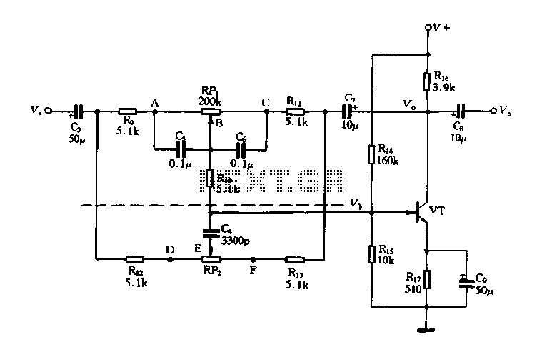
The circuit is a decay feedback tone control circuit that incorporates anti-attenuation feedback action. Its primary function is to enhance or attenuate bass frequencies, although this distinction can sometimes be challenging to perceive. The analysis utilizes the superposition theorem,...
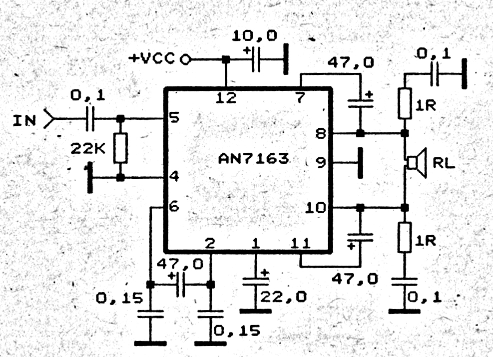
This 5.1 surround amplifier circuit schematic utilizes the IC AN7168 as the primary component. The circuit requires a minimum voltage of 12V and a maximum voltage of 24V, with a recommendation of 12V due to the voltage ratings of...
A telephone line-based audio muting and light activation circuit. Frequently, when listening to music or watching television at elevated volume levels, it becomes difficult to hear a telephone ring, resulting in missed important calls. This circuit is designed to address...
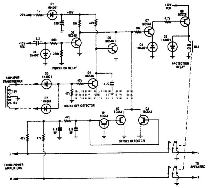
Transistors Q1, Q2, and Q3 monitor the two outputs of the stereo amplifier. If the offsets exceed 2 V, Q7 is turned off, which in turn deactivates Q8 and the normally on relay. Diodes D2 and D5, along with...