
Audio sine-wave generator
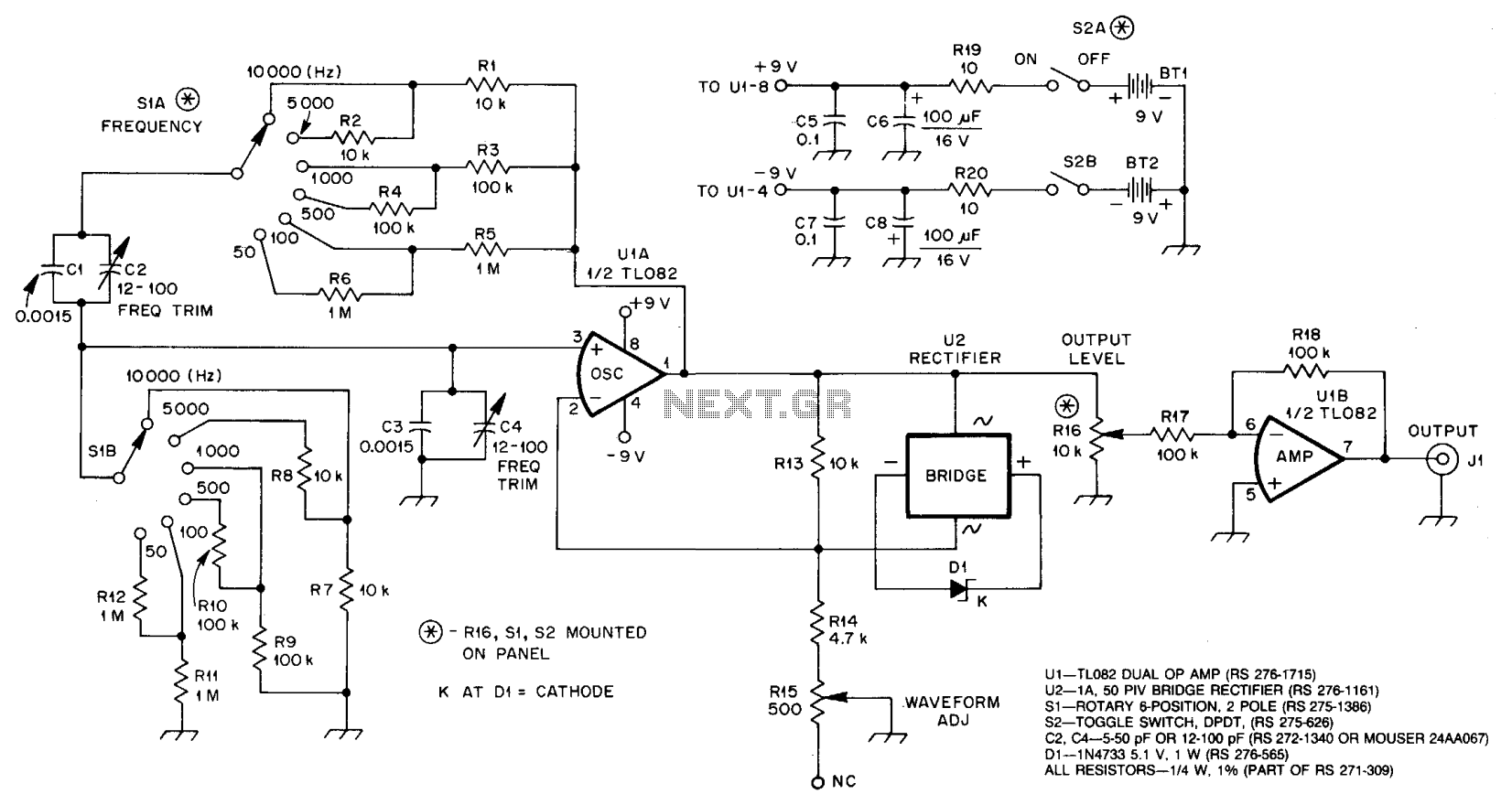
As the voltage at pin 1 of U1 approaches its peak value, D1 enters its Zener breakdown region, effectively providing a resistive load across R13. This action increases the amount of negative feedback around U1, thereby reducing its gain. R15, labeled as WAVEFORM ADJ, allows for the optimization of circuit operation to achieve the lowest distortion. U1B serves to isolate the oscillator from the load. With the specified values for R17 and R18, U1B operates at unity gain.
The circuit described is a Wien Bridge Oscillator, which is a type of electronic oscillator that generates sine waves. The use of U1A as the primary amplifier allows for the generation of oscillations based on the specific characteristics of the Wien bridge network, which consists of resistors and capacitors configured to produce a zero phase shift condition at the desired frequency of oscillation. The selection of resistors through S1A and S1B provides flexibility in tuning the oscillator's frequency, enabling precise control over the output signal.
The automatic gain control provided by U2 and C1 is critical to maintaining stable oscillation. By dynamically adjusting the gain of U1A, the circuit can compensate for variations in component values or environmental conditions that might otherwise lead to instability or distortion in the output waveform. The Zener diode D1 plays a vital role in this feedback loop, ensuring that the gain remains within optimal limits as the signal amplitude changes.
R15, the waveform adjustment resistor, is essential for fine-tuning the circuit's performance. By altering its resistance, the user can minimize harmonic distortion, ensuring a cleaner output signal. The isolation provided by U1B prevents loading effects that could otherwise affect the oscillation characteristics of U1A. Operating at unity gain with the specified resistor values, U1B ensures that the oscillator's output is not influenced by the load, maintaining the integrity of the generated waveform.
Overall, this circuit exemplifies a well-designed Wien Bridge Oscillator, balancing gain, feedback, and component selection to produce a stable and low-distortion sine wave output suitable for various applications in signal generation and testing.U1A, an op amp, oscillates at the frequency at which the phase shift in the Wien bridge network is exactly zero degrees. Changing bridge component values changes the oscillator frequency. In this circuit, we need change only the two resistors to do this. S1A chooses a value among Rl through R6, and SIB similarly selects a value from R7 through R12. U1A must provide enough gain to overcome losses in the bridge, but.not so much gain that oscillation builds up to the point of overload and distortion.
U2 and Cl automatically regulate circuit gain to maintain oscillation. U2 places Dl across R13 with the proper polarity on both positive and negative alterations of the signal at pin 1 of Ul. As the voltage at pin 1 of Ul approaches its peak value, Dl enters its Zener breakdown region, effectively shunting R13 with a resistive load. This increases the amount of negative feedback around Ul, reducing its gain. R15, WAVEFORM ADJ, allows you to optimize circuit operation for lowest distortion. U1B provides isolation between oscillator and load. With the values shown for R17 and R18, U1B operates at unity gain. 🔗 External reference
Related Circuits
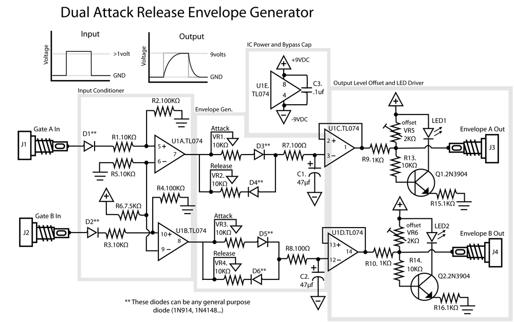
This is a dual Attack/Release envelope generator that has been added to the Modular Benjolin design. While not essential, it provides enjoyable functionality, particularly when used alongside the modular rungle bit output mod. The circuit is straightforward, making it...
This project is a 3 or more lines mixer. For more than 3 inputs you can repeat the input parts (P=10K R=22K). It powered with 9Vdc. The described project is a multi-channel audio mixer designed to handle three or more...
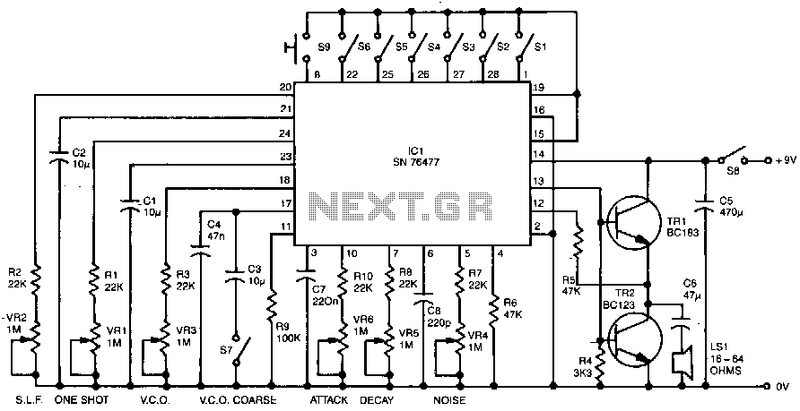
Six preset controls and seven selector switches enable a vast range of different sounds to be produced and altered at will. Such sounds as steam trains chuffing, helicopters flying, bird chirping, and machine guns firing are possible, as well...
By selecting the "ON" mode, the SilverPro© initiates the process of generating colloidal solutions using the preset parameters configured by the user. The unit always recalls the last used presets. During operation, the display alternates between the total elapsed...

A simple yet effective circuit to generate a POTS-compatible ringing voltage can be constructed using National Semiconductor's LM4871 audio amplifier IC along with a dozen passive components. This circuit produces a sine-wave output of 1 W at approximately 70...
The circuit has a flat frequency response from about 20Hz to well over 50Khz. Input sensitivity is 100mV for a full scale deflection on a 100uA meter. Built on two common emitter amplifiers, the first stage has a preset...