
LED Flasher with 555
The described circuit employs a 555 timer IC configured in an astable mode, which is ideal for generating a square wave output. This output can be used to drive one or more light-emitting diodes (LEDs) for visual signaling. The frequency of the blinking can be adjusted by changing the timing components, specifically the resistor and capacitor values. In the standard configuration, a capacitor of 10µF and appropriate resistor values yield a flashing rate of approximately 2 Hz (half a second on, half a second off). By increasing the capacitor value to 22µF, the flashing rate can be reduced to about 1 Hz (one second on, one second off), providing flexibility in the visual output speed.
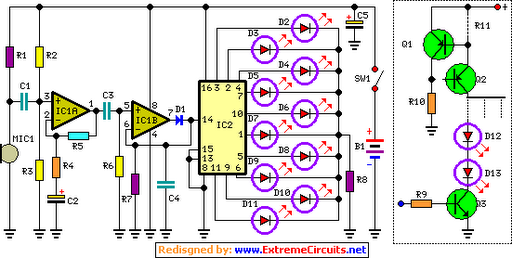
For alternating flashing, the circuit allows for the addition of a second LED. This is accomplished by connecting an additional LED in series with a 330-ohm resistor to designated points on the circuit board, enabling both LEDs to flash alternately. The 555 timer's ability to source or sink up to 200mA of current permits the connection of multiple LEDs in parallel, facilitating a maximum of approximately 18 LEDs for both the standard and alternating configurations. This results in a total potential of 36 LEDs when utilizing the alternating flasher feature.
The schematic for this circuit would typically include the 555 timer, resistors for timing, a capacitor for frequency adjustment, and the LEDs with their respective current-limiting resistors. Proper attention should be given to the power supply to ensure it can handle the total current drawn by the LEDs. Additionally, the circuit layout should minimize interference and ensure stable operation of the 555 timer.This is a very basic circuit for flashing one or more LEDS and also to alternately flash one or more LEDs. It uses a 555 timer setup as an astable multivibrator with a variable frequency. With the preset at its max. the flashing rate of the LED is about 1/2 a second. It can be increased by increasing the value of the capacitor from 10uF to a higher value. For example if it is increased to 22uF the flashing rate becomes 1 second. There is also provision to convert it into an alternating flasher. You just have to connect a LED and a 330ohm as shown in Fig.2 to the points X and Y of Fig.1. Then both the LEDs flash alternately. Since the 555 can supply or sink in upto 200mA of current, you can connect upto about 18 LEDS in parallel both for the flasher and alternating flasher (that makes a total of 36 LEDs for alternating flasher). 🔗 External reference
Related Circuits

To control multiple switches, it is necessary to transmit several bits via infrared (IR) transmission to indicate which key is pressed on the remote control and, consequently, which switch on the switchboard to operate. This project utilizes a commercially...

The circuit is an easy-to-build and use general-purpose Big LED with SPI serial interfacing. It is expandable for multiple digits while utilizing only three wires to receive data from any microcontroller boards. The design incorporates a serial-in-parallel-out shift register,...
The basic circuit illuminates up to ten LEDs in sequence, synchronized with the rhythm of music or speech detected by a small microphone. The expanded version can drive up to ten strips, each consisting of up to five LEDs,...
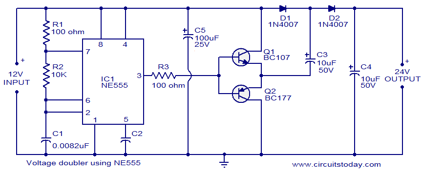
The circuit diagram of a simple voltage doubler using the NE555 timer is presented. In this configuration, the NE555 IC operates as an astable multivibrator at approximately 9 kHz. The bases of two transistors, Q1 and Q2, are connected...

This is a license to use the files to manufacture up to 12 boards. If additional boards are required, please make contact. It is important to note that the order must specify the intent to produce 12 or fewer...
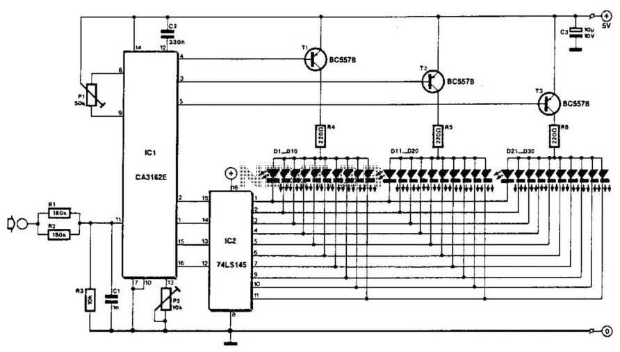
The voltage to be measured is digitized in an analog-to-digital (A/D) converter and then displayed in three decimal digits. The display consists of three groups of 10 LEDs. The meter can only be used for measuring direct voltages. The...