
AN6610 Application Circuit

The AN6610 application circuit is designed for precise motor speed regulation in response to variations in supply voltage and mechanical load. The circuit utilizes feedback control to ensure that the motor operates at a consistent speed, despite external disturbances.
The operation begins with the detection of changes in the supply voltage (Vcc) which can occur due to fluctuations in the mechanical load applied to the motor. These changes lead to variations in the back EMF generated by the motor, which directly influences the motor speed.
To monitor these variations, the circuit employs an adjustable resistor network (R1, R4) that samples the voltage across the motor. This sampled voltage is crucial as it reflects the instantaneous operating conditions of the motor. The error amplifier receives this sampled voltage at its inverting input and compares it with a predetermined reference voltage (VREF) at the inverting input.
The difference between these two voltages generates an error signal, which is processed by the error amplifier. The output of the error amplifier is connected to the base of a transistor that acts as a control element for the motor's supply voltage. By adjusting the base current of the transistor, the output voltage at pin 3 is modulated, allowing for real-time adjustments to the motor's operating conditions.
The feedback mechanism established in this circuit creates a negative feedback loop that stabilizes the motor speed. When the motor speed deviates from the desired setpoint, the error amplifier responds by altering the output voltage, thus correcting the speed. This closed-loop control system is essential for applications requiring precise motor control, ensuring that the motor maintains a consistent performance under varying load conditions.
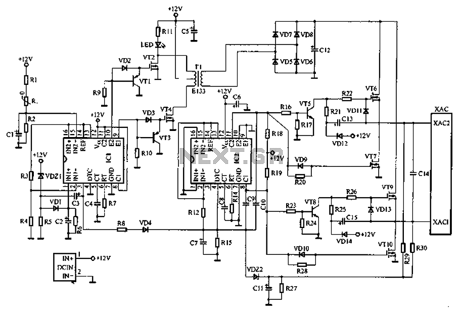
Overall, the AN6610 application circuit provides an effective solution for motor speed control, leveraging the principles of feedback and error amplification to achieve reliable and stable operation.AN6610 Application Circuit It works briefly as follows: When the supply voltage vcc motor mechanical or negative change when the load changes, can cause changes in motor speed. And speed proportional to the anti-electric potential E. Marrow also change accordingly the voltage across the motor also changes. From adjustable resistor 1, 4 on two sampled voltage v ,. Reflects these voltage changes, delivered to the error amplifier inverting input terminal, compare it with the inverting input of the reference voltage VREF, the error amplifier controls the two rear base of the transistor, the output voltage (pin 3) is adjusted. 3-pin output voltage and V.. There was a negative relationship between the feedback control, the results tend to be closed-loop control to maintain a constant speed.
Related Circuits
Car inverter specifications include an input voltage range of DC 10V to 14.5V, output voltage of AC 200V to 220V with a tolerance of 10%, output frequency of 50Hz with a tolerance of 5%, and an output power range...
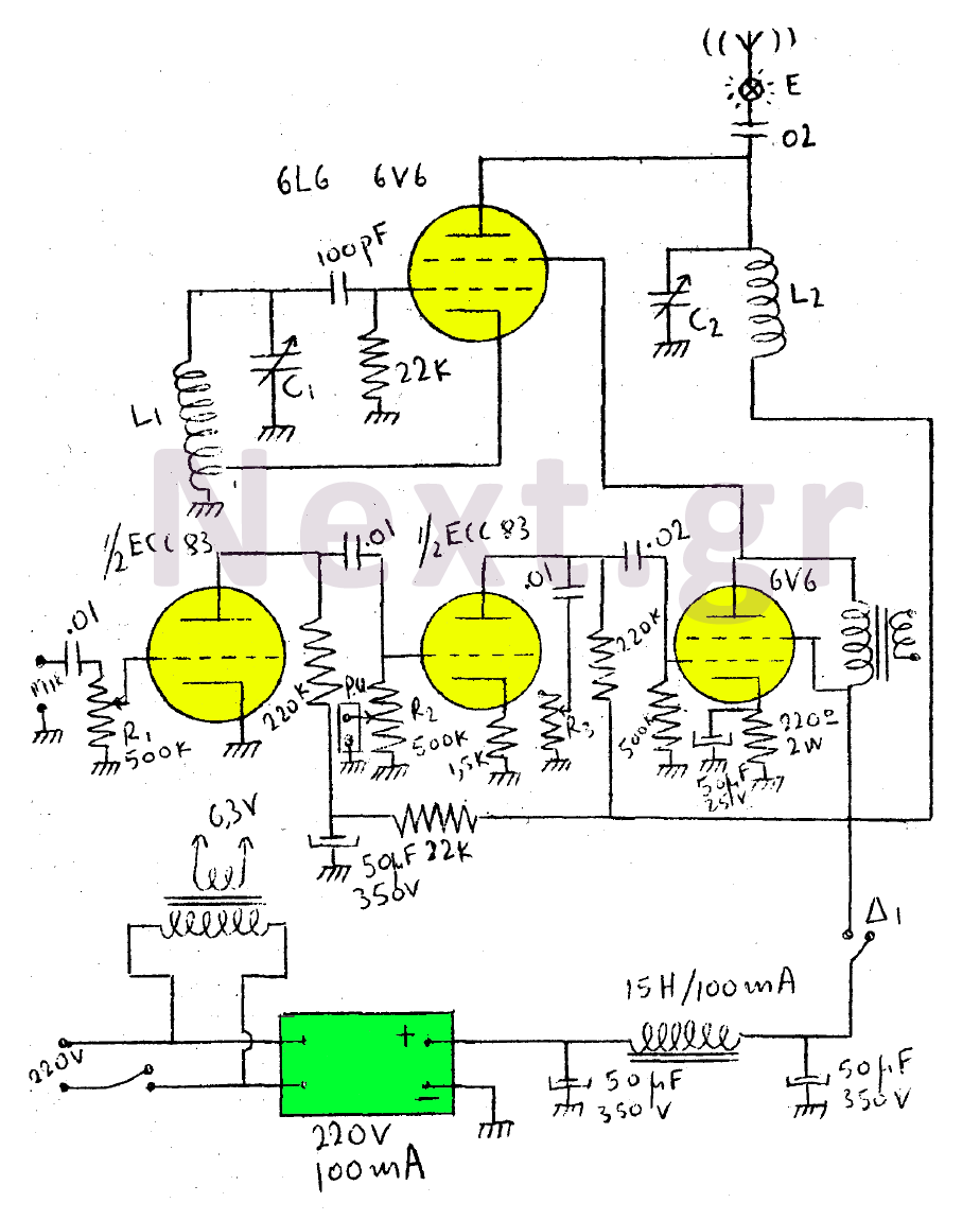
This circuit features a wearer assembly that includes a single lamp, either a 6V6 or 6L6, functioning as both an oscillator and an output amplifier. Coil L1 serves as the medium wave oscillation coil, while coil L2 is composed...
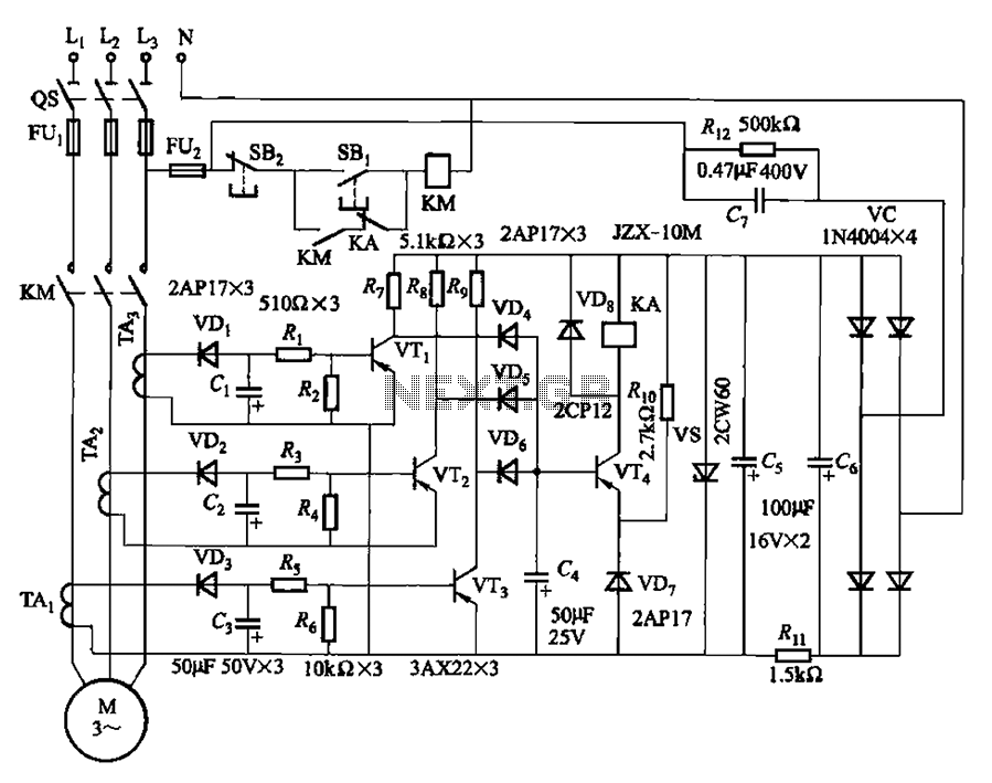
The current detection signal is obtained from three current transformers after rectification and filtering, resulting in three DC voltage outputs. These voltages are applied to transistors VT1, VT2, and VTa between the base and emitter. The signal is amplified...
If expecting an important visitor but needing to step out for a moment, an electronic doorbell memory can be useful to check if someone rang while away. Although it may not indicate whether the expected visitor arrived, a quick...
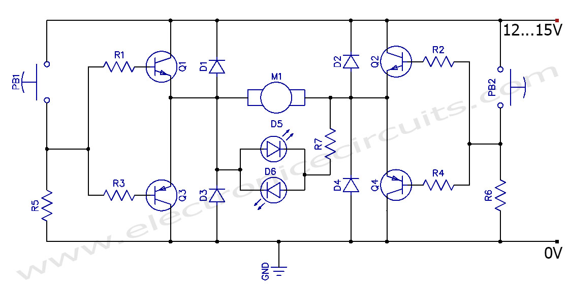
This circuit can control the direction of a DC motor, allowing it to operate in both clockwise and counterclockwise directions (forward and backward). The described circuit employs an H-bridge configuration, which is essential for reversing the polarity of the voltage...
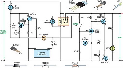
This circuit is designed to switch power to a Peltier cooler in a vehicle. Power is supplied to the load from the vehicle's battery when the ignition switch is on and from an SLA auxiliary battery when the ignition...