
DC Motor Clockwise Anticlockwise Control H-bridge Circuit

The described circuit employs an H-bridge configuration, which is essential for reversing the polarity of the voltage applied to the motor, thereby enabling bidirectional control. The H-bridge consists of four switches (transistors or MOSFETs) arranged in a bridge configuration. When two opposite switches are activated, current flows through the motor in one direction, causing it to rotate clockwise. Conversely, activating the other two switches reverses the current flow, resulting in counterclockwise rotation.
Control signals for the H-bridge can be generated using a microcontroller or a simple control circuit. For example, a microcontroller can provide PWM (Pulse Width Modulation) signals to modulate the speed of the motor in addition to controlling its direction. A push-button switch or a joystick can be used to manually change the direction of the motor, providing an intuitive interface for operation.
Protection features such as flyback diodes are often included in the design to prevent voltage spikes generated by the inductive load of the motor from damaging the control circuitry. Additionally, current sensing can be integrated to monitor the motor's load and prevent overheating or stalling conditions.
This bidirectional motor control circuit is widely used in various applications, including robotics, conveyor systems, and automated machinery, where precise control over motor direction and speed is required.This circuit can control direction of a DC motor. This can operate the motor in both directions (Bi-direction) Clockwise and Anticlockwise (forward and back) 🔗 External reference
Related Circuits
The task involved testing the capacitive properties of food by connecting various edibles to an Arduino. This project, known as BeetBox, was developed by Scott Garner, a student at NYU-ITP, who designed an innovative musical instrument that uses beets...
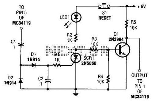
The ear protector is a peak audio detector and shutdown circuit that disables the amplifier through its chip-disable input when the output volume of the amplifier reaches a predetermined level. Although designed for the MC34119 amplifier, the circuit should...
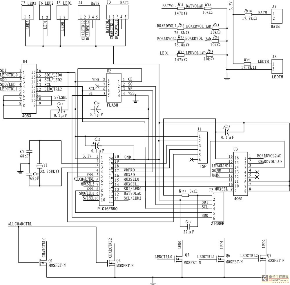
The development of a solar energy street lamp control device has progressed through three stages. The first generation featured a simple and crude function, allowing the light to be turned on or off, but required connection to a light-sensitive...
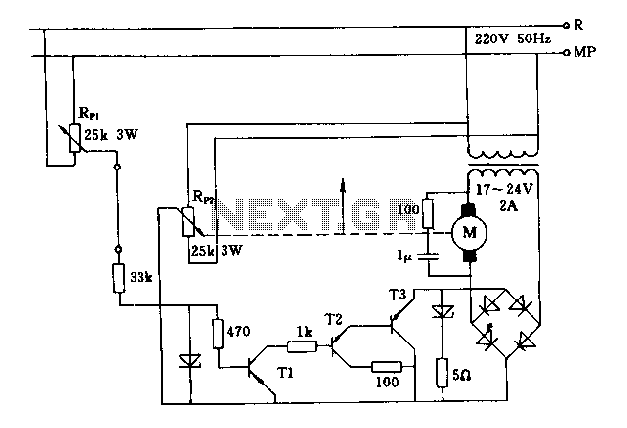
The FIG potentiometer RP2 has a sliding contact that is directly connected to the antenna. The system operates such that only when potentiometers RP1 and RP2 are positioned identically, do the non-conductive transistors and rectifier bridge remain off, resulting...
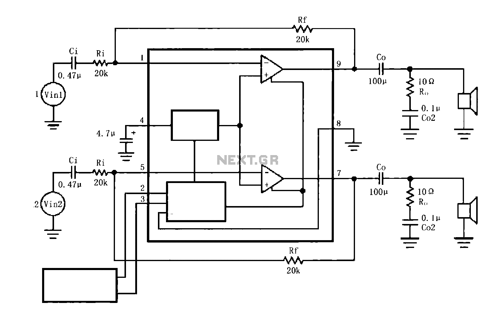
The circuit illustrated is a typical configuration for the LM4916 two-channel amplifier. The left and right channel audio signals are fed into the LM4916, which amplifies them internally. The output is then delivered through a coupling capacitor (Co) to...
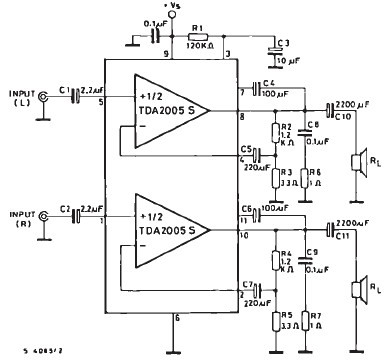
The TDA2005 car audio amplifier circuit is specifically designed for use in devices such as car radios, CD players, and similar equipment. This amplifier is based on the TDA2005 audio integrated circuit (IC), capable of delivering a maximum output...