
Basic reference transistor bias circuit - Mixed Negative feedback
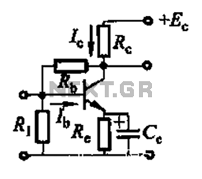
The basic reference transistor bias circuit utilizing mixed negative feedback is a fundamental electronic configuration designed to stabilize the operating point of a transistor. This circuit typically employs a combination of resistive feedback and emitter degeneration to enhance linearity and thermal stability.
In this configuration, a transistor is connected in a common-emitter arrangement, where the input signal is applied to the base terminal. The collector is connected to a power supply, while the emitter is connected through a resistor to ground. The mixed negative feedback is achieved by incorporating resistors that connect the collector to the base, providing a fraction of the output voltage back to the input. This feedback mechanism helps to reduce the gain sensitivity to variations in transistor parameters and temperature changes.
The biasing network is crucial for ensuring that the transistor operates in the active region, preventing it from entering saturation or cutoff during signal variations. The design of the resistor values is critical, as they determine the biasing current and, consequently, the quiescent point (Q-point) of the transistor. Proper selection of these components allows for a stable operation over a range of conditions, making this circuit widely used in amplifier designs and other applications requiring reliable transistor performance.
In summary, the basic reference transistor bias circuit with mixed negative feedback is essential for achieving stable and linear transistor operation, which is vital for a variety of electronic applications. Basic reference transistor bias circuit - Mixed Negative feedback
Related Circuits
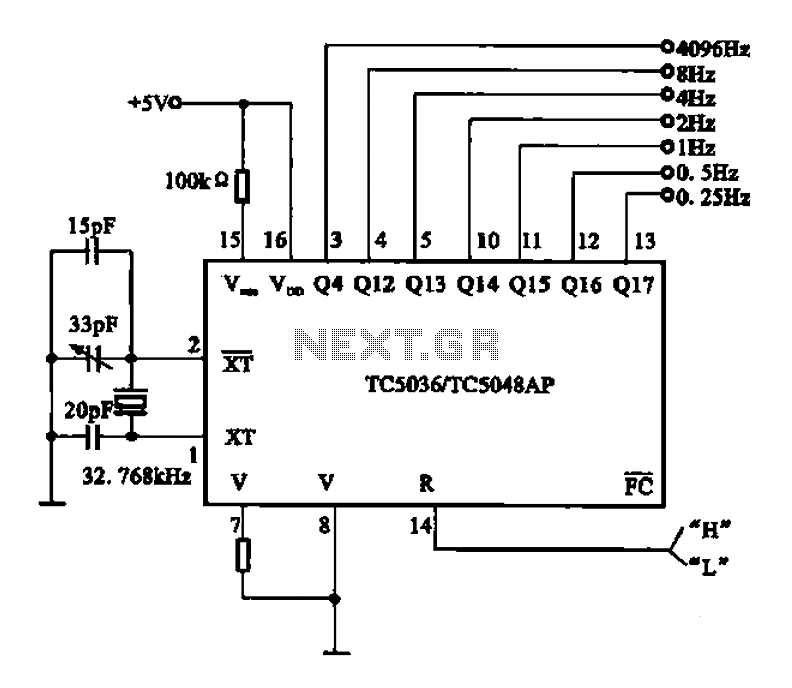
32.768 kHz; In MP3/MP4 devices, mobile phones, laptops, and other digital products, a real-time clock signal generating circuit is utilized, primarily composed of crystal resonators and TC5036/TC5048AP chip oscillators. This setup produces a raw 32.768 kHz crystal oscillator signal,...
Physical motion of some form helps differentiate a robot from a computer. It would be nice if a motor could be attached directly to a chip that controlled the movement. But, most chips can't pass enough current or voltage...

There is an advantage in using continuously active PWM signals. The main reason is that the asynchronous frequencies of the PWM core and microcore can sometimes result in a shortened PWM pulse. The servo recognizes this as a command...

RTD sensors are measured using a precision 24-bit analog-to-digital converter (A/D) that includes a built-in programmable gain amplifier. The connections for 2-wire, 3-wire, and 4-wire RTDs are illustrated. This setup facilitates the connection and measurement of RTDs with amplifiers and...

The super LED flasher consists of two complete LED flasher circuits integrated onto a single circuit board. The first LED flasher is comprised of IC1 and LEDs D1 and D2. IC1 is a 555 timer IC configured as an...

Digital Command Control (DCC) provides significant advantages over traditional DC analog control systems, primarily due to its simplified wiring. DCC enables the individual control of multiple locomotives on the layout without requiring electrical isolation of track sections. The main...