
DC Motor-Driver H-Bridge Circuit

Specialized circuits (motor drivers) have been developed to supply motors with power and to isolate the other ICs from electrical problems. These circuits can be designed such that they can be completely separate boards, reusable from project to project. A very popular circuit for driving DC motors (ordinary or gearhead) is called an H-bridge. It's called that because it looks like the capital letter 'H' on classic schematics. The great ability of an H-bridge circuit is that the motor can be driven in both forward and reverse directions.
An H-bridge consists of four switches arranged in a bridge configuration. These switches can be implemented using transistors, MOSFETs, or relays. The basic operation involves controlling the states of these switches to allow current to flow through the motor in either direction. When two switches on one side of the bridge are closed, current flows through the motor in one direction, causing it to spin. Conversely, closing the switches on the opposite side will reverse the current flow, thus reversing the motor's direction.
In practical applications, the control signals for the H-bridge can be generated by a microcontroller or a dedicated motor driver IC. These control signals can be PWM (Pulse Width Modulation) signals to adjust the speed of the motor by varying the duty cycle. Additionally, H-bridges often include protection features such as diodes to handle back EMF generated by the motor, which protects the control circuitry from voltage spikes.
Moreover, the design of H-bridge circuits allows for easy integration into various projects, making them versatile for robotics, automation, and other applications requiring precise motor control. The modular nature of these circuits means they can be reused across different projects, simplifying the design process and reducing development time.Physical motion of some form helps differentiate a robot from a computer. It would be nice if a motor could be attached directly to a chip that controlled the movement. But, most chips can`t pass enough current or voltage to spin a motor. Also, motors tend to be electrically noisy (spikes) and can slam power back into the control lines when the motor direction or speed is changed. Specialized circuits (motor drivers) have been developed to supply motors with power and to isolate the other ICs from electrical problems.
These circuits can be designed such that they can be completely separate boards, reusable from project to project. A very popular circuit for driving DC motors (ordinary or gearhead) is called an H-bridge. It`s called that because it looks like the capital letter `H` on classic schematics. The great ability of an H-bridge circuit is that the motor can b 🔗 External reference
Related Circuits
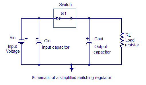
Switching regulators operate by drawing small amounts of energy from the input source and transferring it incrementally to the output. This is achieved using an electronic switch, which functions at a predetermined frequency, acting as a gate between the...
The figure illustrates a digital display pressure measuring circuit diagram. The circuit operates with an additional voltage of approximately 12.8V and draws a current of 30mA. Under maximum gain conditions, the input voltage range is 0.8mV. The zero adjustment...
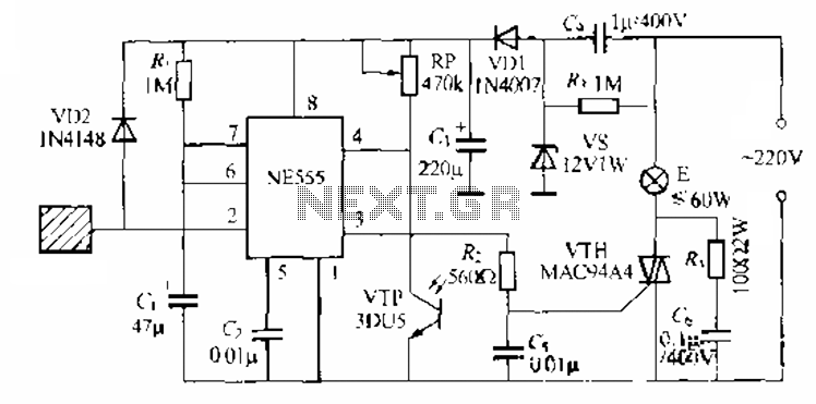
The circuit utilizes a NE553 automatic light sensor composed of 55 groups, allowing lights to turn on when individuals are present and turn off when they leave. The power supply includes VD1, vS, and C, with a 12V DC...

This circuit generates sine and square wave signals with frequencies ranging from below 20 Hz to above 20 kHz. The advantage of this circuit diagram is that the output frequency can be adjusted by varying the variable resistor R6. The...
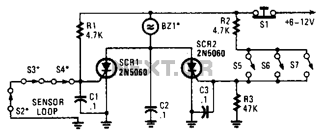
Two SCRs are utilized with two sensor loops. One loop employs series switches, while the other loop employs parallel switches. When a switch is actuated, the SCR is triggered. The alarm is designed to be a non-interrupting type. The circuit...
A band-pass filter permits only signals within a specified frequency range to pass through, while attenuating or suppressing those outside this range. This is characterized by a lower frequency limit and an upper frequency limit. A typical implementation is...