
Data acquisition system circuit
Additionally, a keyboard/display interface circuit has been designed to enable the operator to monitor the temperature changes of each furnace. Four LED displays are utilized for this purpose, with the display buffer units designated as 28H and 29H. The first bit indicates the channel number, allowing for the display of temperatures up to 999 for channels 2 to 4, as per system requirements. The display system supports two operational modes: A) Automatic cycling mode, where the computer automatically samples the annealing temperature for channels 1 to 8 without requiring user intervention to turn off the display; B) Point display mode, which allows the operator to view the temperature of a specific annealing channel at any time. The two display modes can be switched arbitrarily based on user preference.
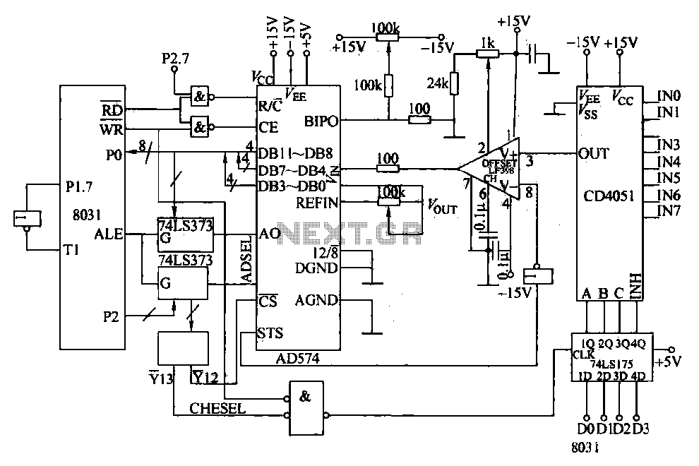
The circuit utilizes an AD574 12-bit A/D converter, which provides high-resolution data acquisition essential for precise temperature monitoring in industrial applications. The integration of the CD4051 multiplexer enables the selection of multiple input channels, facilitating the measurement of temperatures from various sources. The 8031 microcontroller serves as the processing unit, managing data flow and control signals effectively.
The sample/hold circuit is critical for stabilizing the input signal during the conversion process, ensuring that accurate readings are obtained. The STS flag plays a vital role in synchronizing the sample/hold operation with the A/D conversion, allowing for seamless data acquisition. The dual display modes enhance the usability of the system, providing flexibility for the operator to monitor multiple temperature channels either automatically or on-demand.
Overall, this circuit design exemplifies a robust solution for temperature monitoring in industrial settings, leveraging advanced components and thoughtful interface design to meet operational requirements.Converters and data sampling: Figure 27-47 12-bit A/D converter AD574 and 8031 to the interface circuit. Parameters measured by the multi- way switch after CD4051 strobe to sam ple/hold input device. Road in the end which is selected by the multiplexer selection control terminal c, B, A and 1 ban Ji Lin keep control terminal INH. Sample/hold working status by the/VD converter conversion end flag STS state control. When the A/D conversion in progress, STS output is high, the inverted, goes low, to the S/H control logic sealed tapered end (Logic), so that S/H is on hold, this when to start A /: D converter.
Digital converted by 8031 to a data bus twice read CPU registers register. After the conversion, STS from high to low, after inverting goes high, thus the S/H into the sample state. 3) Keyboard/Display Interface Circuit: In order to allow the operator to be able to keep abreast of changes in the temperature of each furnace, designed four LED display monitor.
Let the display buffer unit as 28H and 29H, first, I first bit indicates the channel number: 2 to 4 exhibition to display the temperature up to 999. According to the needs of the system. The method is designed to display in two ways: A Automatic cycle, at the invitation of ways, the computer can automatically sampled 1-8 annealing temperature number do not ask to turn off the display; B point show that the operator can any view at any time for a one annealing temperature, and the two display modes can be arbitrarily switched.
Related Circuits
An advantage of a photogate over a sound trigger is that the former activates based on the exact position of the object that interrupts the beam. For instance, the shape of a snapped elastic cord can be captured as...
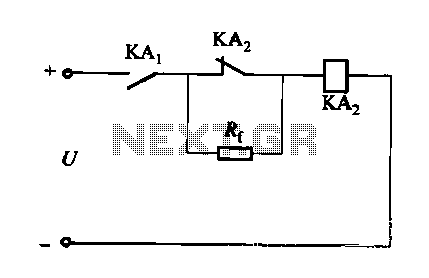
A DC relay or contactor is utilized to enhance the excitation pull-in and release mechanisms in a circuit. The relay circuit, as depicted in Figure 6-28, facilitates improved return line efficiency. When the control relay KAi is activated, its...
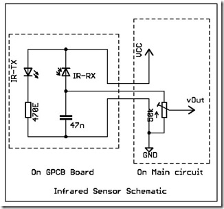
The following circuit illustrates a simple infrared sensor module circuit diagram. Features include a simple infrared sensor module and flame detection. The simple infrared sensor module circuit operates by utilizing an infrared (IR) transmitter and receiver pair. The IR transmitter...
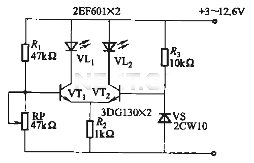
When the battery voltage is within the range of 7 to 12.6V, the light-emitting diode VLi illuminates, maintaining a consistent brightness. If the battery voltage drops below 7V, VLi begins to emit a red light, and the brightness of...
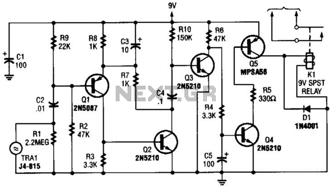
A GC Electronics P/N J4-815 transducer is utilized to receive 40-kHz acoustic remote-control signals. The receiver activates a relay to control another circuit. The GC Electronics P/N J4-815 transducer is designed specifically for the reception of 40-kHz acoustic signals, which...
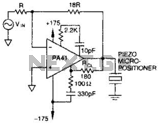
The PA41 from Apex Microtechnology is utilized to drive a piezoelectric micropositioner. The drive voltage is less than 20 V peak-to-peak at the input. The PA41 is a high-performance power amplifier designed specifically for driving piezoelectric devices, which require precise...