
Piezo Micropositioner Driver Circuit

The PA41 is a high-performance power amplifier designed specifically for driving piezoelectric devices, which require precise control of voltage and current to achieve accurate positioning. This amplifier is capable of delivering a high output voltage, which is essential for the operation of piezoelectric micropositioners that typically operate within a limited voltage range.
In the context of a piezoelectric micropositioner, the PA41 amplifies the input signal to produce a drive voltage that can effectively control the micropositioner's movement. The specification of a drive voltage of less than 20 V peak-to-peak indicates that the amplifier is being used within a safe operating range, ensuring that the piezoelectric element is not subjected to excessive voltage that could lead to damage or non-linear behavior.
The circuit configuration would typically involve connecting the output of the PA41 to the input terminals of the piezoelectric micropositioner, while the input of the PA41 would be connected to a signal source that provides the control signal. This setup allows for dynamic control of the micropositioner's position, enabling applications in fields such as optics, robotics, and precision manufacturing.
To ensure optimal performance, it is crucial to consider factors such as the power supply requirements for the PA41, the bandwidth of the input signal, and any necessary feedback mechanisms to stabilize the system. Additionally, proper thermal management should be implemented to maintain the reliability of the amplifier during extended operation. Overall, the PA41 serves as a robust solution for driving piezoelectric micropositioners, facilitating precise and controlled movements in various applications. The PA41 from Apex Microtechnology is used here to drive a piezoelectric micropositioner. The drive voltage is less than 20 V p-p at input.
Related Circuits
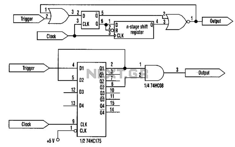
This approach utilizes a Hip-Hop, a shift register, and two gates (A). Before the one-shot pulse, the output of the NOR gate is 0. Consequently, the data input of the D-type flip-flop is equivalent to the trigger. When a...
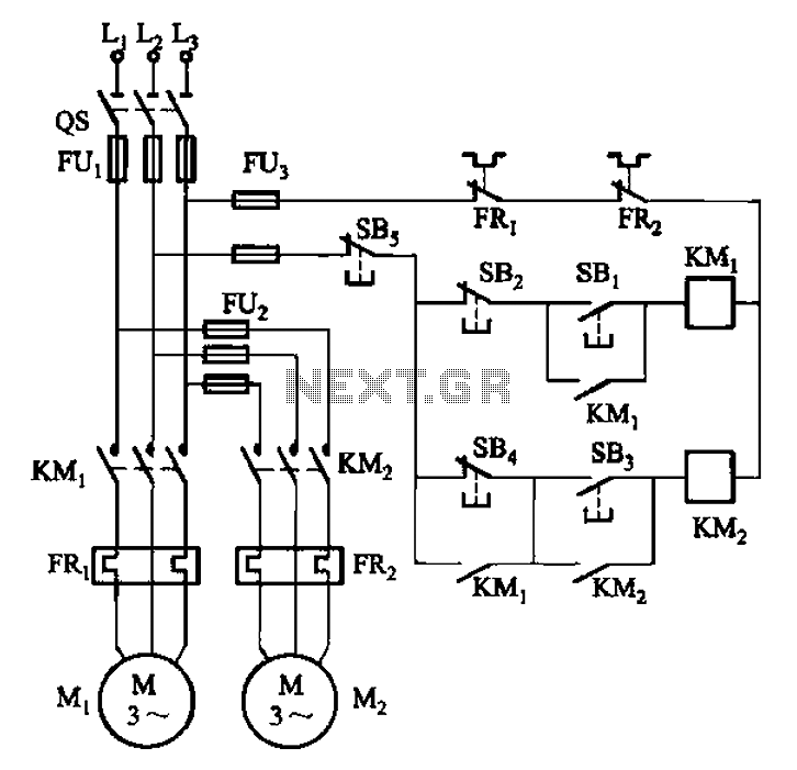
The circuit depicted in Figure 3-84 allows two electric motors to be started independently. The motors can only be activated after pressing the main stop button (SBz) to release contact KMi. Following this, the auxiliary stop button (SB4) can...
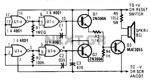
An external horn-type speaker is optimal for this circuit. However, such devices demand significant power, so this sounder should only be employed in alarm circuits utilizing at least a 6-A SCR as the sounder driver. The circuit incorporates a...
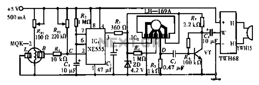
The circuit operates using the MQK-2 gas sensor, which detects the presence of combustible gases or smoke through surface adsorption. When gas is detected, the inter-electrode resistance (BL) decreases significantly. This change in resistance affects the voltage at node...
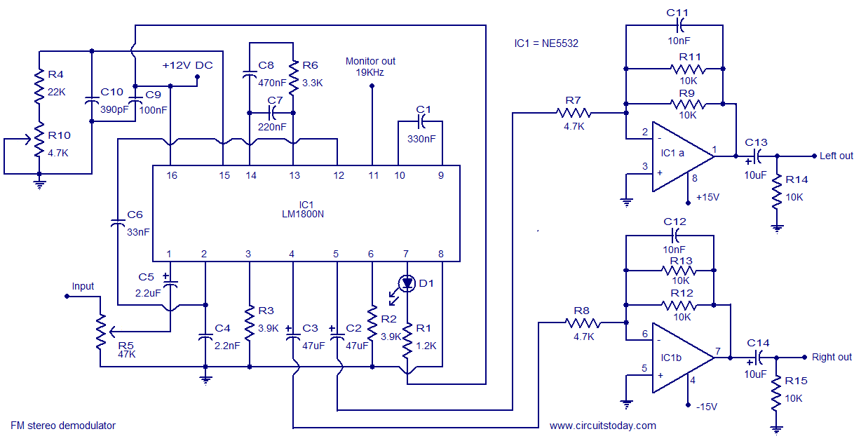
The following circuit illustrates the LM1800 IC Integrated FM Stereo Demodulator Circuit. Features include excellent sound quality and high-quality FM stereo. The LM1800 Integrated Circuit (IC) serves as a highly effective FM stereo demodulator, designed to deliver superior audio performance...
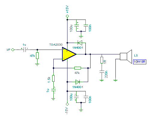
Connecting two TDA2030 through inexpensive power transistors allows for the creation of an amplifier capable of delivering higher power. This can be achieved by utilizing the component values specified in the schematic. To implement this circuit, two TDA2030 integrated circuits...