
Through a small pulse transformer output of one transistor trigger circuit
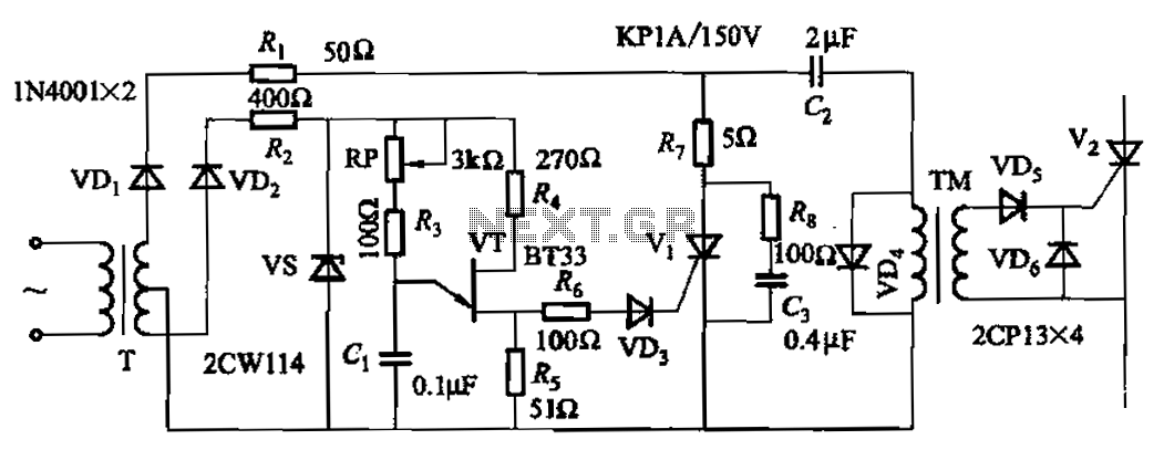
The circuit incorporating the adjustment potentiometer RP is designed to facilitate precise control over the phase shift of a pulse signal. This phase shift circuit operates within a specified range of 0 to -1600 degrees, which indicates the potential for significant timing adjustments in signal processing applications. The use of an adjustment potentiometer enhances the sensitivity of the phase shift, allowing for fine-tuning to achieve desired operational characteristics.
In practical applications, this circuit can be utilized in various electronic systems that require precise timing adjustments, such as in communication systems, audio processing, or modulation schemes. The potentiometer RP serves as a variable resistor, enabling the user to alter the resistance in the circuit, thereby changing the voltage levels and consequently affecting the phase of the output pulse.
The design may include additional components such as capacitors and operational amplifiers to stabilize the circuit and ensure the output remains within the desired parameters. Properly selecting the values for these components is critical to achieving the intended phase shift and maintaining signal integrity. Overall, the phase shift circuit with the adjustment potentiometer RP is a valuable tool in electronic design, providing versatility and control over signal timing.Adjustment potentiometer RP, can change the pulse phase shift range. The phase shift circuit is in the range of 0. -1600 Higher sensitivity.
Related Circuits
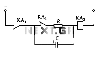
To fulfill the requirements of a control loop, it is often necessary to utilize an electromagnetic relay or a transistor relay to either accelerate or delay an action, thereby forming an acceleration or delay circuit. The circuit depicted in...
This small transistor tester employs a simple visual indication system to perform a quick go/no-go check on both NPN and PNP transistors. If the tested device is a functional NPN transistor, the green LED (D1) will flash, while the...

This stereo amplifier utilizes the NE5517/A and features an excellent tracking accuracy of 0.3 dB, which is typical. The offset can be adjusted using the potentiometer, Rp. For AC-coupled amplifiers, the potentiometer can be substituted with two 5.1 k...
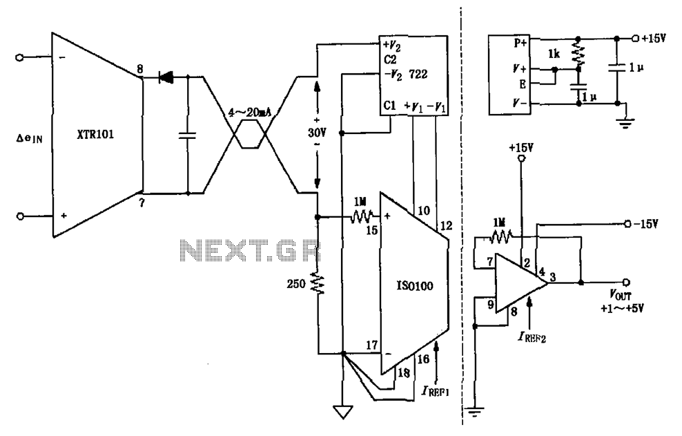
The circuit combines the XTR101 with the ISO100 isolation amplifier to transform a 4-20 mA current signal into a voltage output ranging from +1V to +5V while providing power supply isolation. It features excellent anti-jamming capabilities, making it suitable...
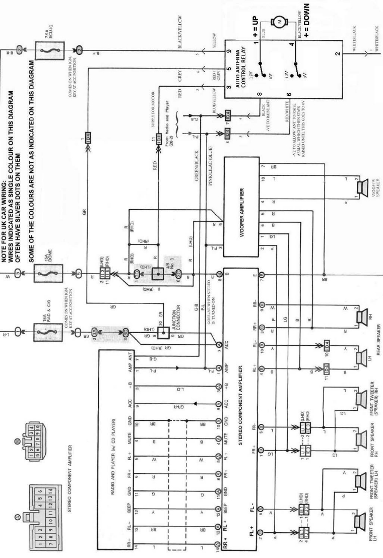
The following circuit illustrates an electrical circuit diagram for the MR2 MKII electric aerial. Features include control by an Aerial Control Relay, which consists of... The MR2 MKII electric aerial circuit is designed to facilitate the automatic operation of the...
This triac-based 220V AC motor speed controller circuit is designed for controlling the speed of small household motors, such as drill machines. The motor speed can be adjusted by altering the setting of P1, which determines the phase of...