
Door touch switch circuit (CD4069) schematic
")
The touch lamp switch circuit leverages the properties of CMOS technology to facilitate a user-friendly interface for controlling lighting. The high input impedance of the CMOS gates means that minimal current is drawn from the input source, making it sensitive to touch activation. When a user makes contact with the designated area of the circuit, the input level changes, which is detected by the inverters.
The CD4069 inverters serve as the core of the circuit, where each inverter not only inverts the input signal but also contributes to the overall behavior of the circuit. The series arrangement of inverters (D1 to D3) enhances the signal processing capability by providing amplification and ensuring that the output maintains a stable state once activated. The feedback element, which includes resistors and capacitors, plays a critical role in maintaining this state, effectively creating a bistable multivibrator configuration. This feedback mechanism allows the circuit to "lock" into its current state, enabling the lamp to remain on or off until the next touch is detected.
The small DC relay in the circuit acts as a switch for the lamp, allowing it to control higher power loads while being driven by the low-power output of the CMOS inverters. When the circuit is triggered by touch, the relay is energized, closing the circuit to the lamp and causing it to turn on. Releasing the touch will not immediately turn off the lamp due to the locking mechanism, ensuring that the lamp remains on until the input condition changes again.
Overall, this touch lamp switch circuit exemplifies the effective use of CMOS technology in creating responsive, low-power control systems suitable for various applications in lighting and automation.CMOS gate has a high input impedance, resistance by human contact, you can make it the input level is changed, triggering gates toggled. The circuit is the use of this feature of its composition one case touch lamp switch, the circuit as shown in FIG. Circuit consists of a six-CD4069 inverter and a small DC relays, CD4069 three inverters Dl ~ D3 series combination of resistance and capacitance coupled through the feedback element, both to ensure signal transmission, but also to achieve a locking circuit.
Related Circuits

There are important considerations when using additional memory, but it is certainly feasible. The MP3 player project utilizes 32 megabytes of memory. However, using more memory necessitates careful planning. The key factor is that the 8051 processor has a...
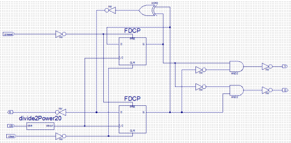
Create a new project by selecting the New Project option from the Getting Started menu or by selecting File > New Project. This opens a dialog box where the desired project name and location can be entered. Choose a...
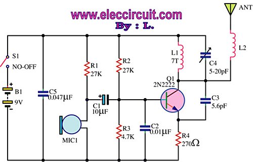
This is an FM wireless transmitter circuit designed to operate a microphone without the need for a cable connecting the microphone to the amplifier. The FM wireless transmitter circuit typically consists of several key components: a microphone, an oscillator, a...
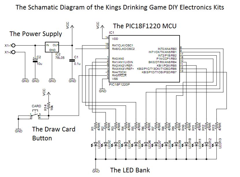
This circuit was designed approximately four months ago and has been developed into a kit for others to use. The circuit in question appears to be a well-thought-out design that has been packaged into a kit format, making it accessible...
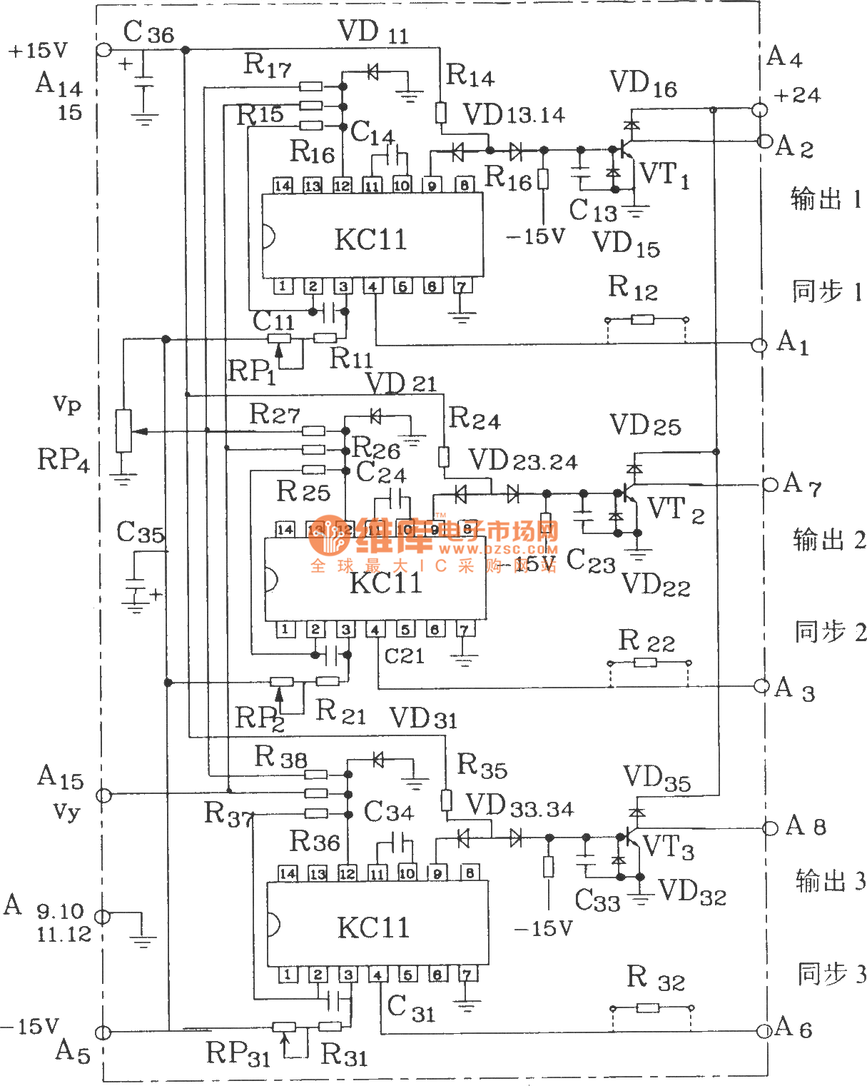
The KCZ3 is an integrated three-pulse triggering component designed for use in three-phase half-bridge inverters. Each phase output pulse can reliably drive a high-power thyristor and is adaptable to various phase voltages. The electrical parameters are as follows: Phase...
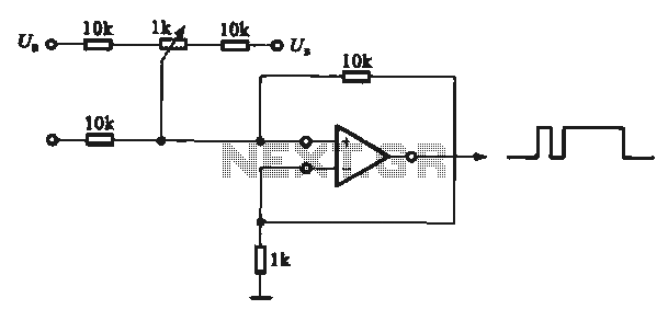
This circuit demonstrates the application of various types of pulse signal generating circuits using operational amplifiers. The circuit utilizes operational amplifiers (op-amps) to create different forms of pulse signals, which are essential in many electronic applications, including waveform generation, timing...