
Pulse signal generating circuit

The circuit utilizes operational amplifiers (op-amps) to create different forms of pulse signals, which are essential in many electronic applications, including waveform generation, timing circuits, and signal modulation. The design typically includes configurations such as astable multivibrators, monostable multivibrators, and Schmitt triggers, each serving a unique purpose in pulse generation.
In an astable multivibrator configuration, two op-amps are used to produce a continuous square wave output. This configuration relies on the feedback network of resistors and capacitors to determine the frequency and duty cycle of the output pulse. The output can be adjusted by changing the values of the resistors and capacitors in the feedback loop.
A monostable multivibrator, on the other hand, produces a single pulse output in response to an external trigger signal. This circuit typically uses one op-amp and a timing capacitor to define the width of the output pulse. The duration of the pulse can be modified by altering the capacitor value or the resistor connected to the timing circuit.
Schmitt triggers are employed to convert noisy or slowly varying signals into clean, fast transitions. This is achieved by introducing hysteresis into the input-output relationship, allowing for a more stable and reliable output pulse. The configuration of the Schmitt trigger can also be adjusted by selecting appropriate resistor values to control the threshold levels.
Overall, the pulse signal generating circuit using operational amplifiers is a versatile tool in electronics, allowing for precise control over timing and waveform characteristics in various applications.It shows the use of various forms of pulse signal generating circuit operational amplifier.
Related Circuits
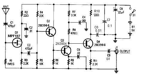
A simple active antenna can be designed using this electronic circuit diagram. This active antenna utilizes transistors and a few common electronic components. In the practice of short-wave frequency reception, a general rule is that a longer antenna will...
The amplifier's gain is nominally 20 dB. Its frequency response is primarily influenced by the values of a few components, mainly C1 and R1. The schematic diagram's component values yield a frequency response of ±3.0 dB from approximately 120...

The circuit diagram and detailed explanation of a simple aircraft radio circuit are provided below. The simple aircraft radio circuit typically consists of several key components that work together to facilitate communication between the aircraft and ground stations or other...
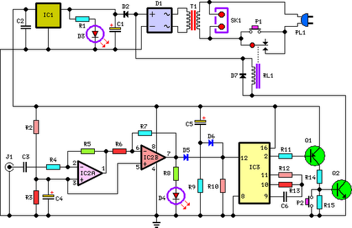
This circuit deactivates an amplifier or any connected device when a low-level audio signal at its input is absent for at least 15 minutes. Pressing P1 turns the device on, supplying power to any appliance connected to SK1. The...
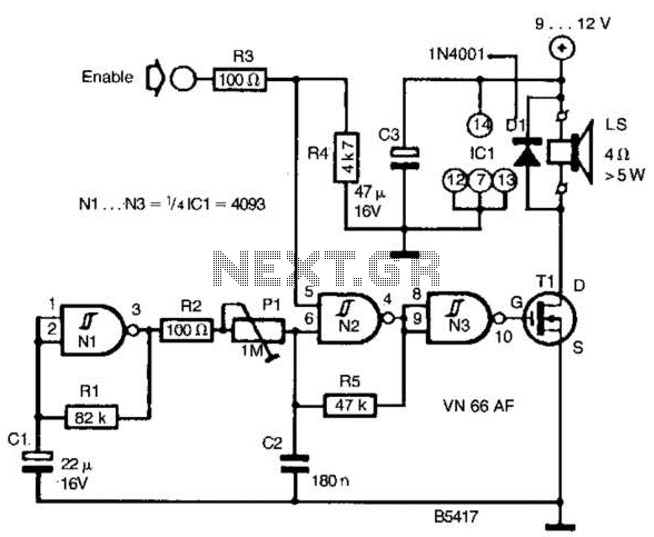
A CD4093 chip and several components form a siren oscillator that drives power MOSFET Tl. A speaker is directly powered by this device. The siren is activated by a logic high signal applied to the ENABLE input. The circuit comprises...
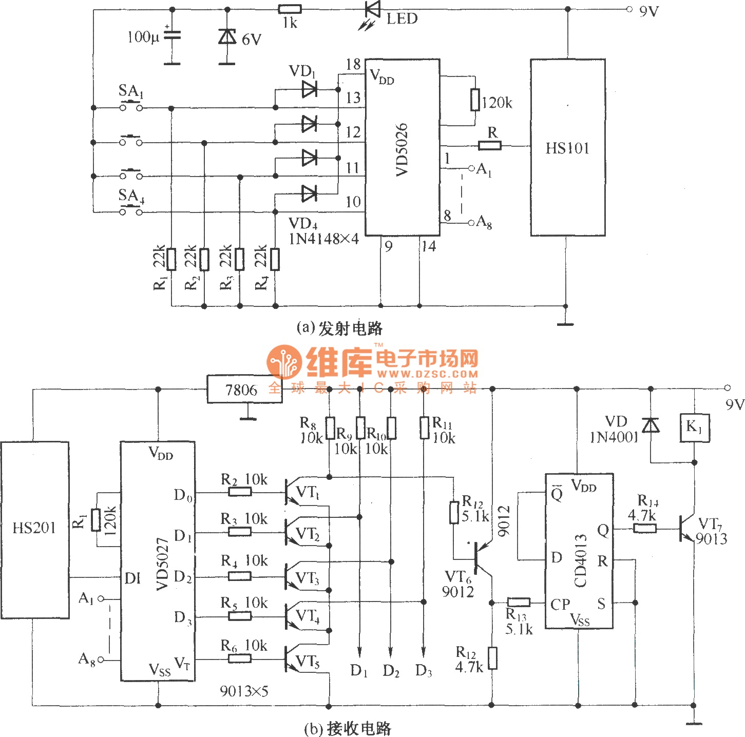
HS101 and HS201 are small radio transceiver components operating at a frequency of 280 MHz, designed for digital signal transmission. They provide a control distance ranging from 30 to 100 meters. All components, including the antenna, are integrated into...