
Latch Switch
This circuit utilizes a non-locking push switch (S1) to control the activation of a load, which can be represented by various components such as a resistor (R5) and a diode (D1), or potentially a lamp or relay. The circuit is designed such that the load remains activated until the power supply is interrupted. An optional switch (S2) can be included to break the power supply to the circuit, allowing for a reset mechanism. If S2 is excluded, the only method to reset the circuit would involve disconnecting the power source, such as unplugging a battery or disconnecting from an electrical outlet.
Upon initial power application, or when S2 is toggled, the capacitor (C1) begins to charge through the base-emitter junction of the transistor (Q1). This charging process generates a brief positive pulse at the base of Q1, which causes Q1 to enter saturation. In the saturated state, the collector-emitter voltage of Q1 approaches zero volts, effectively allowing current to flow through the load. With Q1 in this state, the second transistor (Q2) remains off, preventing any unwanted activation of additional components in the circuit.
The design of this circuit is particularly useful in applications where a momentary switch is desired to control a load that remains on until power is removed. The inclusion of C1 allows for a smooth transition during the activation phase, ensuring that the load is turned on reliably. The optional switch S2 provides flexibility for the user, enabling a straightforward method to reset the circuit without needing to physically disconnect the power supply. Overall, this circuit offers a simple yet effective solution for controlling various loads in electronic applications.In this circuit a non-locking push switch is used to activate a load. The load remains switched on until power is removed from the circuit. The load is represented by R5 and D1, but could be a lamp, a relay or another circuit. S2 breaks power to the circuit but could be omitted altogether. If S2 is left out, then reset would be by disconnecting the power; this would mean unplugging the battery if battery powered or disconnecting from the electrical outlet. When first plugged in (or S2 is operated) C1 charges via the base emitter junction of Q1 and hence a brief positive pulse is applied. Q1 will switch on and be saturated, its collector emitter voltage being close to zero volts. Q2 is therefore off, and the 🔗 External reference
Related Circuits
The overhead detector (fire alarm) circuit utilizes a precision integrated temperature sensor, the LM35 (IC1), which offers an accurate linear output. The overhead detector circuit is designed to monitor ambient temperature levels for fire detection purposes. The core component of...
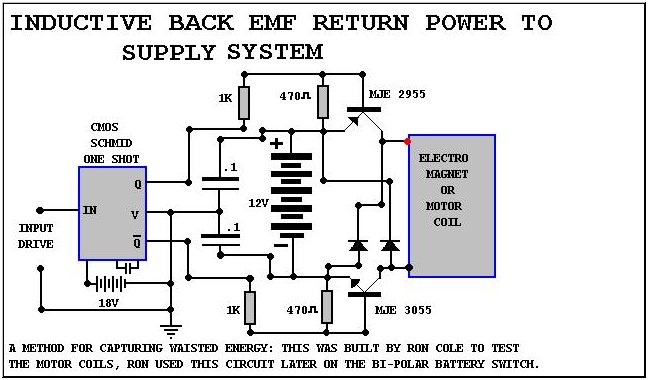
The starting point for the experiments was a switching device constructed by John Bedini for the Tesla Symposium. The objective was to enhance this switching device for compatibility with standard car or motorcycle batteries. The switching device designed by John...
Self-switching power supply. One of the main features of the regulated power supply circuit being presented is that, although a fixed-voltage regulator LM7805 is used in the circuit, its. The self-switching power supply circuit utilizes the LM7805 voltage regulator to...
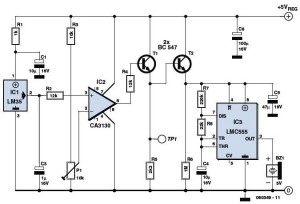
This light sensor switch circuit enables the automatic activation of a lamp when ambient light levels are low, such as during nighttime. The circuit keeps the lamp illuminated for a predetermined duration. When transistors T4 and T5 are activated,...
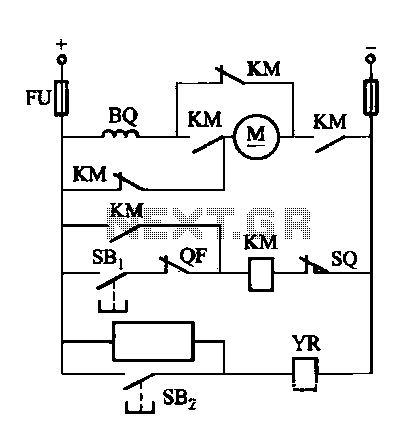
The DW16M-630 type excitation switch operates with both DC and AC power. The circuit for DC operation is illustrated in Figure 7-60, while the circuit for AC operation is shown in Figure 7-61. The BQ single-phase series motor M...
Speaker relay delay controlling circuit for audio amplifier The speaker relay delay controlling circuit is designed to manage the connection of speakers to an audio amplifier, ensuring that the speakers are activated only after a specified delay. This delay serves...