
Light sensor switch circuit

This light sensor switch circuit is designed for efficient operation in environments where automatic lighting control is desired. The circuit leverages a phototransistor (T3) to detect ambient light levels. When light is present, T3 conducts, which in turn keeps T5 off, preventing the lamp from being activated. The base-emitter junction of transistor T2 is strategically placed in parallel with T3, ensuring that T2 remains off during daylight conditions. As darkness sets in, resistor R7 provides the necessary base current to T2, allowing it to turn on.
Once T2 is activated, it initiates the counting process within the integrated circuit IC1, which is likely a timer or counter IC. The internal oscillator of IC1 generates clock pulses that are counted, and during this time, the lamp remains illuminated. The duration for which the lamp stays on is determined by the timing configuration of the circuit, which may involve additional components not explicitly detailed in the description, such as resistors and capacitors connected to the IC.
After the predetermined time has elapsed, the output of Q13 transitions to a high state, which subsequently turns off T4. This action deactivates the relay, causing the relay's LED to extinguish and the lamp to turn off, effectively completing the cycle. The entire circuit is designed to operate directly from the 220V AC mains supply, making it convenient for residential or commercial lighting applications. The diodes (D1 to D5) play a crucial role in converting the AC voltage to a usable DC voltage for the circuit, while capacitor C4 smooths out any voltage fluctuations, ensuring stable operation of the circuit components. This design emphasizes energy efficiency and automation, making it suitable for various lighting control scenarios.This light sensor switch circuit allows the automatic connection of a lamp when the light is low (at nightfall) and will maintain the lamp ON for a certain period of time. From the moment that T4 and T5 are opened, relay`s LED start to light and powers the lamp. As soon as one of the transistors is blocked the lamp will go OFF. The phototransistor T3 will be the one that blocks T5 if there is light that falls on T3. The T2 ²s base-emitter junction is connected in parallel with T3 and so will be blocked as long there is light. T2 will continuously resest IC1 whose counter outputs will be in 0 ³ state. When the night falls R7 provides base current for T2 and the transistor starts to conduct. The counter can now starts to count the impulses from the internal oscillator and in this time the light will bulb will stay lit.
After a time, when the output of Q13 goes in state 1 ³ T4 is blocked. This causes the relay`s LED to go off and the lamp too. There is no need for external power supply because the light sensor switch is powered directly from the 220V mains. D1 D5 diodes rectifies the voltage and C4 filters it. 🔗 External reference
Related Circuits

AM radio shows the IF amplifier and detector circuit. The mixer receives the intermediate frequency output signal from the transformer after the device. This signal is applied to the base of the intermediate frequency transistor VT4. The collector load...
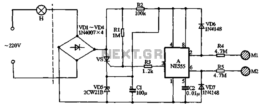
The circuit illustrated in the figure features a dashed line on the left, representing a standard lighting circuit, while the right side is responsible for the dual functionality of touch activation using the NE555 timer. Components VD1 through VD4...

This is a cost-effective DIY option for a hearing aid. It should not be considered a replacement for a genuine hearing aid prescribed by an audiologist. Amplifying all sounds and frequencies, or using it continuously in loud environments, may...

A CMOS clock circuit is capable of driving a multi-digit gas discharge display. This simple circuit does not include an alarm feature but allows for a flashing colon to indicate morning and afternoon. The circuit requires seven drive circuits...

Light Sensitive Staircase Switch with Triac. The operation of the third circuit is quite similar, except that it incorporates photo sensitivity. The circuit is illustrated in the schematic. When there is insufficient light... The light-sensitive staircase switch circuit utilizes a...

When we step on the car's brake, then together with the classic rear STOP, the third STOP which is situated in the middle of the back half of the car also switches ON. This is the classic function, found...