
Time-On Touch Switch
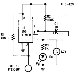
The described circuit employs a 555 timer IC configured in monostable mode, which is ideal for generating a single output pulse in response to a trigger signal. The touch terminal serves as the input for the trigger, which, when activated, causes the 555 timer to generate a high output on pin 3. This output is used to drive the LED1 and the piezoelectric buzzer BZ1. The duration of the output pulse is determined by the resistor R2 and the capacitor C, following the formula T = 1.1 * R2 * C, where T is the time period in seconds.
The circuit is designed to be powered by batteries, which adds versatility and portability, allowing it to be used in various applications without reliance on a fixed power source. The inclusion of a 10-ohm resistor (R1) at the trigger input enhances the circuit's sensitivity, ensuring that even minimal contact at the touch terminal can initiate the activation sequence. This characteristic makes the circuit suitable for applications where ease of use and quick response are critical.
Adjustments to the values of C1 and R2 enable users to customize the ON-time according to specific needs, making the circuit adaptable for different scenarios. The simplicity and effectiveness of this design lend it to various uses, from simple alarm systems to interactive installations, where user engagement is achieved through tactile interaction. The circuit is built around a 555 oscillator (Ul), which is turned on when a trigger is applied by touching the touch terminal to pin 2 of Ul. When activated, LED1 and BZ1 (a piezoelectric buzzer) turn on for the time period set by the values of R2 and C. The ON-time of the touch circuit can be altered by changing the values of Ci and R2. This touch switch can be powered from batteries so that it need not be near a 60-Hz power source for triggering.
The extremely small amount of current supplied to the trigger input through the 10- resistor. Rl, makes the input circuitry very sensitive to any external loading, and it is easily triggered by touching the pickup. 🔗 External reference
Related Circuits
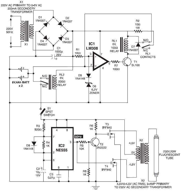
When mains power is absent, relay RL2 remains in a de-energized state, supplying battery power to the inverter section through its normally closed contacts and switch S1. The inverter section consists of IC2 (NE555), configured in astable mode to...
Tasks such as jewel cutting and polishing require workers to repeatedly turn on and off two electrical appliances in succession for different services on the same workpiece. This process can be cumbersome, as it demands full concentration on the...
A switch-mode power supply provides ±15V or ±12V at 0.5A output from a 4.5V to 12V input. The wide input voltage range allows flexibility to be powered from a regulated DC voltage. The switch-mode power supply (SMPS) described operates within...
Half of RL1 and RL2 manage the switching mechanism, while the other half connects to an application. The relays operate at 200 ohms above ground, with one terminal referenced to positive voltage, which deactivates them. RL1, when off, applies...
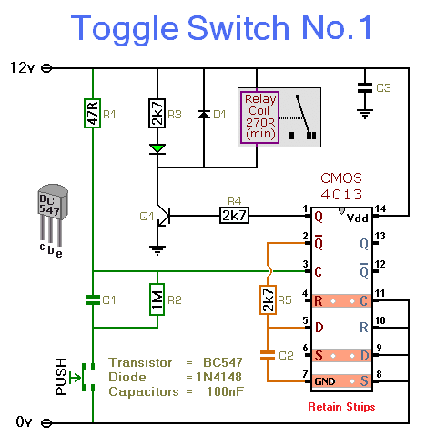
This simple circuit will energize and de-energize a relay with the push of a button. Pressing the button once will energize the relay, while pressing it a second time will de-energize the relay. The accompanying circuit provides a solid...
Just to prove that transistors can also be useful in logic situations; this is a data latch and indicator which also is a data switch and has a bidirectional input/output port which can be read or switched. If the...