
Data Switch with LED

This circuit represents a basic data latch configuration using two NPN transistors, which can function as a bistable multivibrator. The key components include two transistors (Tr1 and Tr2), a light-emitting diode (LED), a 12 kΩ resistor, a 220 kΩ resistor, and a 4.7 nF capacitor. The circuit operates on the principle of positive feedback, where the state of the output is maintained until an external condition changes it.
In the initial state, when Tr2 is off, a small current flows through the LED, the 12 kΩ resistor, and the 220 kΩ resistor to the base of Tr1, turning it on. This action keeps Tr2 off, as it is dependent on the state of Tr1. The capacitor (4.7 nF) charges during this state, storing energy.
When the switch is closed, the capacitor discharges, providing a pulse to the base of Tr1. This momentarily reduces the base current of Tr1, allowing it to turn off. As a result, Tr2 is turned on due to the positive feedback mechanism, causing the LED to light up. The circuit's state can be determined by measuring the voltage at the input; if the input is driven high or low, the LED will respond accordingly by turning on or off.
This configuration can be adapted to use a relay in place of the LED for applications requiring higher current or voltage control. The circuit exemplifies how transistors can be effectively utilized in logic applications, showcasing their versatility in electronic design.Just to prove that transistors can also be useful in logic situations; this is a data latch and indicator which also is a data switch and has a bidirectional input/output port which can be read or switched. If the second transistor is off, a small currrent will flow via the LED, 12K and 220K to make Tr1 conduct, keeping Tr2 off.
At the same time, the 4n7 charges up. Now, if the switch is closed, the current pulse of the 4n7 discharging should bring Tr1 out of saturation (as it has only limited base drive) and cause Tr2 to turn on. The LED lights and as Tr2 is on, no current flows into Tr1's base, so the circuit has changed state. The circuit's state can be read from the voltage at the input and if the input is forced high or low,the LED will be forced on or off.
Of course you could use relay instead of the LED. 🔗 External reference
Related Circuits
When the tank is empty, the wires within it are open-circuited, causing the 180K resistor to pull the switch low, resulting in the switch being open and the LEDs being OFF. As water begins to fill the tank, the...
This voltage-controlled frequency divider circuit produces lower frequency pulses that depend on the control voltage, with synchronous rising edges for the input and output pulses. Typically, such frequency dividers utilize a monostable circuit connected between an inverted output and...

Audiostrobe glasses are utilized alongside light and sound machines, as well as certain brainwave entrainment software. The glasses are equipped with built-in LEDs. Audiostrobe glasses are designed to enhance the sensory experience provided by light and sound machines, which are...
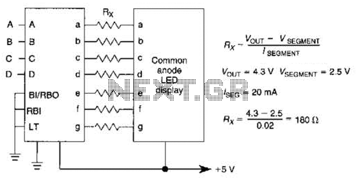
An IC1, such as the 7447, drives a common anode 7-segment LED display. The current-limiting resistor R must restrict the segment current to the rated value at the maximum supply voltage. A sample calculation is provided. The 7447 integrated circuit...
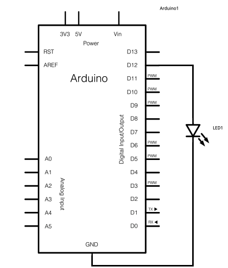
The schematic for this project consists of adding a single 5mm LED to one digital output port on the Arduino. The main components in the schematic include the Arduino Uno, a 5mm LED, and a USB cable. The left...

The circuit utilizes a Darlington-type phototransistor as the sensing element, which enhances sensitivity to low light levels, making it suitable for detecting reflected light signals. When the Darlington phototransistor is exposed to light, its resistance decreases, causing the voltage...