
uPC1237 speaker protection schematic

The uPC1237 integrated circuit is designed to facilitate efficient power management and protection in audio amplifier applications. Its ability to operate within a voltage range of 25V to 60V allows for versatile use across different amplifier designs. The relay driver circuit, with its specified current limit and the necessity for a current limiting resistor (R12), ensures that the relay operates safely without overheating, thus extending the lifespan of both the relay and the integrated circuit.
The power-on delay feature is critical in audio applications, as it minimizes the risk of audible noise during the amplifier's startup phase. The choice of R7 and C3 values allows for customization of the delay period, enabling designers to tailor the circuit to specific audio requirements. This is especially important in high-fidelity audio systems where any noise can detract from the listening experience.
The AC power detection mechanism enhances the safety of the audio system by ensuring that the speakers are disconnected during power transitions. This feature not only protects the speakers from potential damage due to sudden changes in output but also contributes to a more seamless user experience. The rapid discharge of capacitor C2 is a key aspect of this functionality, allowing for quick response to changes in power state.
Overall, the uPC1237 provides a robust solution for managing power and protecting audio systems, with detailed specifications and design considerations that allow for effective implementation in various amplifier configurations. The provided tables serve as essential references for designers to make informed decisions regarding component selection and circuit design, ensuring optimal performance and reliability of the audio system.uPC1237 by a single power supply, operating voltage range of 25v ~ 60v, usually the direct use of the amplifier as a positive power source + Vcc power. Relay coil voltage is DC 24v, because foot relay driver-side current limit is 80mA, in energize the relay timely, pin voltage is about 0v, if the average voltage Vcc 24v, must be inserted step-down current limiting resistor R12, the relay and integrated circuit are not caused by over-current heat damage, the correspondence between the resistance R12, the average power consumption and Vcc voltage in Table 1. Buffs can look-up table 1 to determine the average voltage value R12 according to vcc own amplifier. uPC1237 foot end is power-on delay, determined by R7, c3 boot parameters quiet time after that is energized until the amplifier circuit reaches a stable equilibrium, let the delay circuit relay contacts connected speakers.
This can eliminate the power-up impact noise, increased c3 or R7 extended boot mute time. uPC1237 feet supply side, the maximum limit is 8v. When Vcc is not the same, R8 respective different resistance, determined look-up table 1. uPC1237 foot AC power detection terminal for the amplifier off mute. When the amplifier power switch is off, the transformer secondary AC voltage immediately disappear, c2 small capacitor discharges through foot resistance quickly, pin voltage drops rapidly, internal circuit control relay, the output of the amplifier and the speakers disconnected to prevent during the transition the power output zero level when the speaker out of balance current impact (ie impact noise off) after a power outage. foot maximum limit voltage 10v, when the monitored power amplifier transformer secondary winding AC voltage values are different, the partial pressure of the current limiting resistor R6 respective different values, are too big too small speaker protection circuit will not work, Ac AC voltage and resistance R6 correspondence between Table 2.
Related Circuits
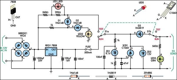
This 8V DC power supply is designed for use with high-end electronic equipment. It includes full over-voltage protection to safeguard against regulator failure, whether in the supply itself or in the connected device. The circuit employs a standard full-wave...
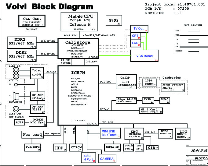
Laptop schematic diagram featuring DDR1 and DDR2 memory slots, a mobile CPU with a 478 Celeron architecture, an ICH7M chipset, an audio circuit utilizing the G1431Q component, a Codec ALC268, an operational amplifier G1412, a modem MDC card, integrated...
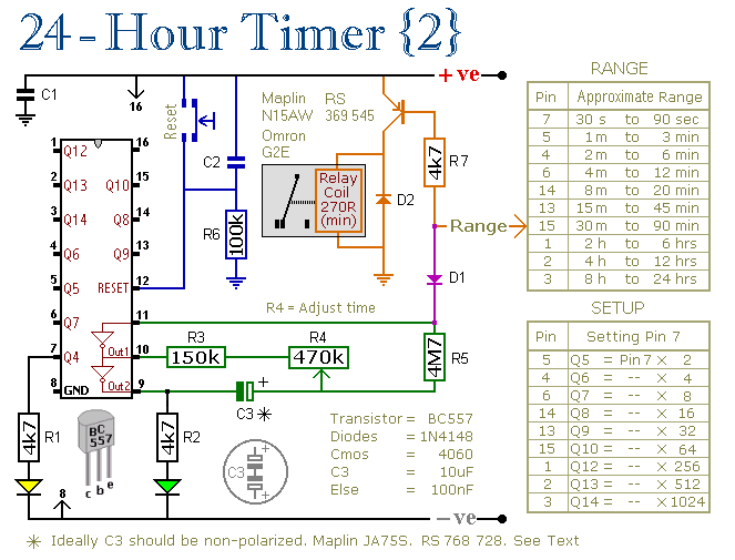
These two circuits are multi-range timers that offer periods of up to 24 hours and beyond. They can function as repeating timers or single-shot timers. Both circuits are fundamentally the same, with the primary distinction being their behavior in...
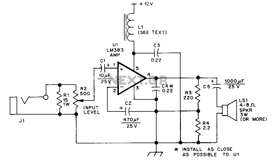
The LM383 is an audio power amplifier capable of delivering up to 8 watts of audio output. Resistor R1 serves as a load resistor for the audio output of a hand-held transceiver. Resistor R2 can be implemented using two...
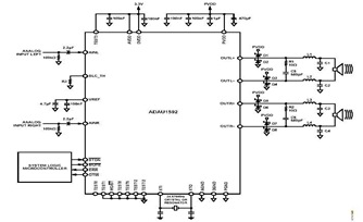
This is a typical stereo application circuit schematic of the ADAU1592, a 2-channel, bridge-tied load (BTL) switching audio power amplifier. The ADAU1592 can be utilized in flat panel televisions, PC audio systems, and mini-component applications. The ADAU1592 is designed to...
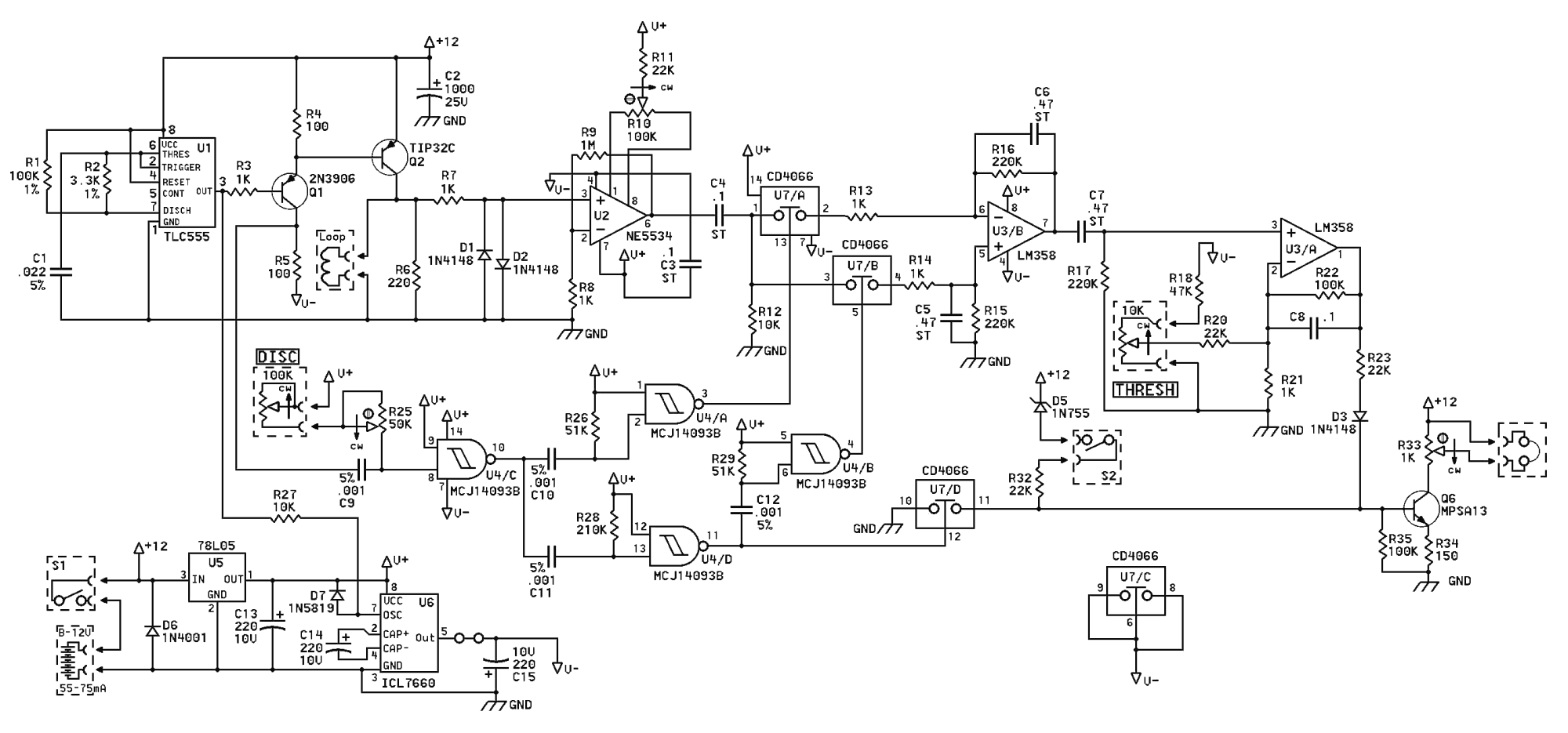
If the TIP32C (Q2) transistor becomes excessively hot, consider replacing it with an IRF9640 MOSFET. It is advisable to experiment with different resistor values for R6 to determine the optimal resistance (a 390-ohm resistor is recommended). A trim potentiometer...