
Two Simple 24-Hour Timer Circuit Schematics
The multi-range timer circuits utilize the CMOS 4060 binary counter, which is adept at providing precise timing intervals through its adjustable oscillator frequency. The design allows for flexibility in application, catering to both single-shot and repeating timer functionalities. The choice between Version 1 and Version 2 hinges on power consumption preferences during operation and post-timer activity.
The oscillator's frequency adjustment via R4 is critical in determining the timing accuracy and flexibility of the device. The output behavior can be tailored based on the application requirements, making this circuit suitable for various timing applications. The omission of D1 for repeating mode simplifies the design, allowing for continuous operation without interruption.
The setup tables serve as a valuable tool for users, facilitating quick calculations for desired timing intervals. The example provided illustrates how to achieve a specific timing output using straightforward calculations. The emphasis on not using the on-board relay for mains voltage switching highlights the importance of safety and proper circuit isolation, ensuring that users are aware of potential hazards.
Capacitor selection is also addressed, emphasizing the need for suitable components to maintain circuit integrity. The use of back-to-back capacitors to simulate non-polarized behavior offers a practical solution for circuit designers. The optional reset button and the recommendation for power consumption reduction after setup further enhance the usability of the circuit.
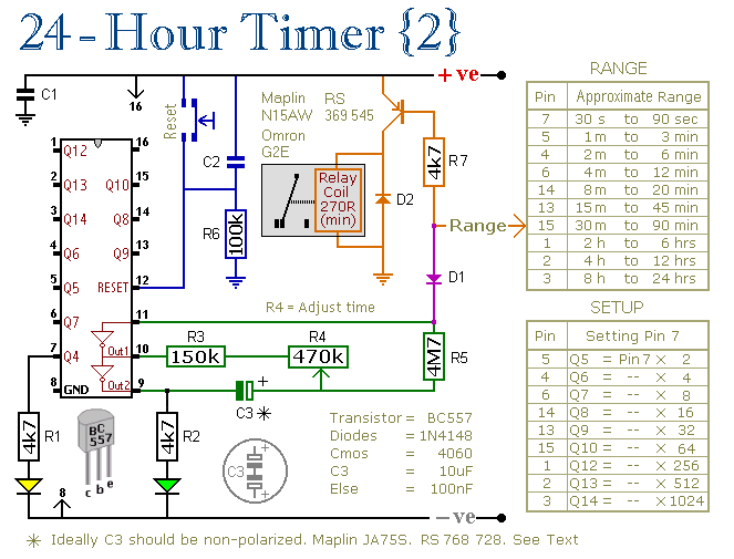
Overall, the multi-range timer circuits are versatile, efficient, and user-friendly, making them suitable for a wide range of applications in timing and control systems. The comprehensive support material provided ensures that users can effectively construct and utilize the timer circuits with confidence.These two circuits are multi-range timers offering periods of up to 24 hours and beyond. They can be used as repeating timers - or as single-shot timers. Both circuits are essentially the same. The main difference between them is their behaviour in single-shot mode. In single-shot mode - when the preset time has elapsed - Version 1 energizes the r elay and Version 2 de-energizes the relay. The first uses less power while the timer is running - and the second uses less power after the timer has stopped. Pick the one that best suits your application. The Cmos 4060 is a 14-bit binary counter. However - only ten of those bits are connected to output pins. The remaining bits - Q1, Q2, Q3 and Q11 - do exist. You just can`t reach them. By adjusting R4 you can alter the frequency of the oscillator. So you can control the speed at which the count progresses. In other words - you can decide how long it will take for any given output pin to go high. If you want to use the timer in repeating mode - simply leave out D1. The count will carry on indefinitely. And the output pin will continue to switch the transistor on and off - at the same regular time intervals.
Using "Trial and Error" to set a long time period would be very tedious. A better solution is to use the Setup tables provided - and calculate the time required for Pin 7 to go high. The Setup tables on both schematics are interchangeable. They`re just two different ways of expressing the same equation. For example, if you want a period of 9 Hours - the Range table shows that you can use the output at Pin 2.
You need Pin 2 to go high after 9 x 60 x 60 = 32 400 seconds. The Setup table tells you to divide this by 512 - giving about 63 seconds. Adjust R4 so that the Yellow LED lights 63 seconds after power is applied. This will give an output at Pin 2 after about 9 Hours. Do not use the "on-board" relay to switch mains voltage. The board`s layout does not offer sufficient isolation between the relay contacts and the low-voltage components. If you want to switch mains voltage - mount a suitably rated relay somewhere safe - Away From The Board.
Ideally C3 should be non-polarized - but a regular electrolytic will work - provided it doesn`t leak too badly in the reverse direction. Alternatively - you can simulate a non-polarized 10uF capacitor by connecting two 22uF capacitors back to back - as shown.
The reset button is optional - but it should NOT be used during setup. The time it takes for the Yellow LED to light MUST be measured from the moment power is applied. Although R1, R2 and the two LEDs help with the setup - they are not necessary to the operation of the timer. If you want to reduce the power consumption - disconnect them once you`ve completed the setup. The timers were designed for a 12-volt supply. However - provided a suitable relay is used - both circuits will work at anything from 5 to 15-volts.
Applying power starts the timer. And it can be reset at any time by a brief interruption of the power supply. The Support Material for this circuit includes a step-by-step guide to the construction of the circuit-board - a parts list - a detailed circuit description - and more. 🔗 External reference
Related Circuits
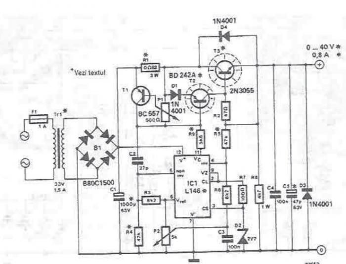
An adjustable laboratory power supply capable of providing an output voltage range from 0 to 60 volts can be constructed using the provided circuit diagram. This power supply can utilize the LM723 chip for lower voltage applications or, for...

The ongoing debate regarding the superiority of valves versus transistors is not the focus here. However, for those undecided, this simple amplifier serves as an excellent test. It employs a valve as a pre-amplifier and a MOSFET in the...
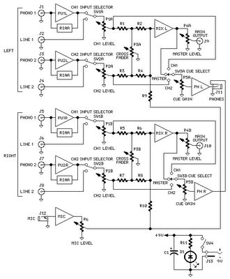
The mixer circuit features two line inputs and two microphone inputs, along with two line outputs. The microphone inputs are designed for low-impedance dynamic microphones with an impedance range of 200-1000 ohms. This simple mixer was specifically designed to...
This operational amplifier (opamp) is available at a low cost. The AD8099 is a very fast opamp with a slew rate of 1600 V/µs and features high-impedance inputs with low input capacitance. Its bandwidth is sufficiently large that at...

The circuit comprises an infrared sensor control circuit, a relay control circuit, a music generating circuit, and additional components. It is applicable for use in infrared alarms, timing control, and various other applications. The circuit design integrates several functional modules...
The micropower circuit automatically provides shutdown, power-up, and low-battery lockout functions without requiring software or operator control. The micropower circuit is designed to manage power efficiently in battery-operated devices, ensuring optimal functionality while conserving energy. The shutdown feature is activated...